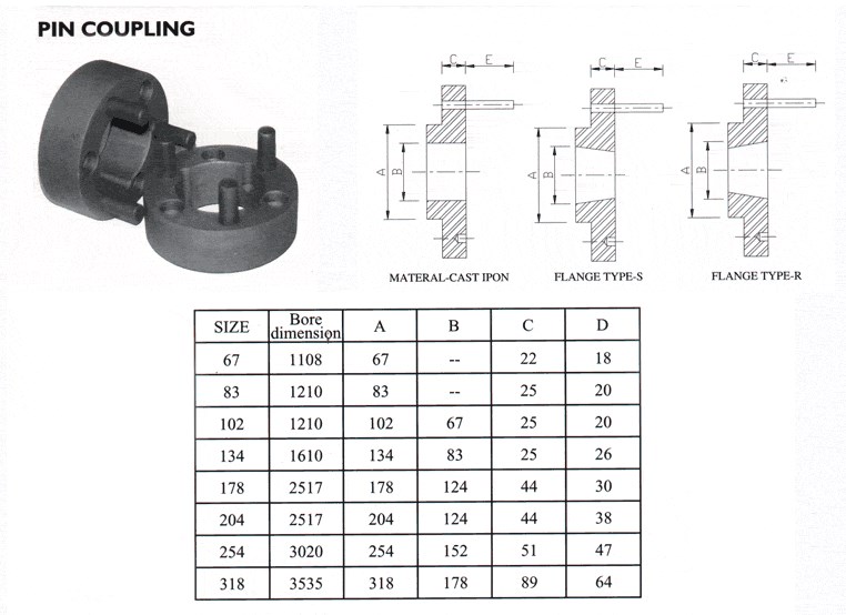
Product Description
Flexible flex Fluid Chain Jaw flange Gear Rigid Spacer PIN HRC MH NM universal Fenaflex Oldham spline clamp tyre grid hydraulic servo motor shaft Coupling
Product Description
The function of Shaft coupling:
1. Shafts for connecting separately manufactured units such as motors and generators.
2. If any axis is misaligned.
3. Provides mechanical flexibility.
4. Absorb the transmission of impact load.
5. Prevent overload
We can provide the following couplings.
| Rigid coupling | Flange coupling | Oldham coupling |
| Sleeve or muff coupling | Gear coupling | Bellow coupling |
| Split muff coupling | Flexible coupling | Fluid coupling |
| Clamp or split-muff or compression coupling | Universal coupling | Variable speed coupling |
| Bushed pin-type coupling | Diaphragm coupling | Constant speed coupling |
Company Profile
We are an industrial company specializing in the production of couplings. It has 3 branches: steel casting, forging, and heat treatment. Main products: cross shaft universal coupling, drum gear coupling, non-metallic elastic element coupling, rigid coupling, etc.
The company mainly produces the industry standard JB3241-91 swap JB5513-91 swc. JB3242-93 swz series universal coupling with spider type. It can also design and produce various non-standard universal couplings, other couplings, and mechanical products for users according to special requirements. Currently, the products are mainly sold to major steel companies at home and abroad, the metallurgical steel rolling industry, and leading engine manufacturers, with an annual production capacity of more than 7000 sets.
The company’s quality policy is “quality for survival, variety for development.” In August 2000, the national quality system certification authority audited that its quality assurance system met the requirements of GB/T19002-1994 IDT ISO9002:1994 and obtained the quality system certification certificate with the registration number 0900B5711. It is the first enterprise in the coupling production industry in HangZhou City that passed the ISO9002 quality and constitution certification.
The company pursues the business purpose of “reliable quality, the supremacy of reputation, commitment to business and customer satisfaction” and welcomes customers at home and abroad to choose our products.
At the same time, the company has established long-term cooperative relations with many enterprises and warmly welcomes friends from all walks of life to visit, investigate and negotiate business!
How to use the coupling safely
The coupling is an intermediate connecting part of each motion mechanism, which directly impacts the regular operation of each motion mechanism. Therefore, attention must be paid to:
1. The coupling is not allowed to have more than the specified axis deflection and radial displacement so as not to affect its transmission performance.
2. The bolts of the LINS coupling shall not be loose or damaged.
3. Gear coupling and cross slide coupling shall be lubricated regularly, and lubricating grease shall be added every 2-3 months to avoid severe wear of gear teeth and serious consequences.
4. The tooth width contact length of gear coupling shall not be less than 70%; Its axial displacement shall not be more significant than 5mm
5. The coupling is not allowed to have cracks. If there are cracks, it needs to be replaced (they can be knocked with a small hammer and judged according to the sound).
6. The keys of LINS coupling shall be closely matched and shall not be loosened.
7. The tooth thickness of the gear coupling is worn. When the lifting mechanism exceeds 15% of the original tooth thickness, the operating mechanism exceeds 25%, and the broken tooth is also scrapped.
8. If the elastic ring of the pin coupling and the sealing ring of the gear coupling is damaged or aged, they should be replaced in time.
Certifications
Packaging & Shipping
/* March 10, 2571 17:59:20 */!function(){function s(e,r){var a,o={};try{e&&e.split(“,”).forEach(function(e,t){e&&(a=e.match(/(.*?):(.*)$/))&&1
| Standard Or Nonstandard: | Nonstandard |
|---|---|
| Shaft Hole: | 19-32 |
| Torque: | <10N.M |
| Bore Diameter: | 19mm |
| Speed: | 8000r/M |
| Structure: | Rigid |
| Samples: |
US$ 999/Piece
1 Piece(Min.Order) | |
|---|
Can Pin Couplings Be Used in Both Horizontal and Vertical Shaft Arrangements?
Yes, pin couplings can be used in both horizontal and vertical shaft arrangements. These couplings are designed to accommodate angular misalignment, parallel misalignment, and axial movement, making them versatile for various shaft orientations.
In horizontal shaft arrangements, where the shafts are aligned on the same horizontal plane, pin couplings can efficiently transmit torque while allowing for flexibility to accommodate minor misalignments and shaft movements. The pins and flexible elements in the coupling enable angular displacement and radial flexibility, ensuring smooth power transmission even if the shafts are not perfectly aligned.
In vertical shaft arrangements, where the shafts are aligned on a vertical plane, pin couplings can also be used effectively. The coupling design allows for axial movement, which is crucial in vertical applications where the shafts may experience expansion or contraction due to thermal changes or other factors. The flexible nature of pin couplings allows them to handle these axial movements without compromising the coupling’s performance.
Whether in horizontal or vertical arrangements, pin couplings are commonly used in various industrial applications, including pumps, compressors, conveyors, and other rotating machinery. They are known for their simplicity, ease of installation, and ability to provide reliable power transmission while accommodating misalignment and shaft movement.
When using pin couplings in either arrangement, it is essential to ensure proper alignment and regular maintenance to maximize their performance and service life. Additionally, considering factors like torque requirements, operating conditions, and environmental considerations will help in selecting the appropriate pin coupling for a specific application.
How Does a Pin Coupling Handle Angular, Parallel, and Axial Misalignment?
A pin coupling is designed to handle different types of misalignment, including angular, parallel, and axial misalignment. The unique construction of pin couplings allows them to accommodate these misalignments without compromising the efficiency and performance of the connected equipment.
1. Angular Misalignment: Angular misalignment occurs when the axes of the driving and driven shafts are not parallel but intersect at an angle. Pin couplings can tolerate angular misalignment because of their flexible and floating pin design. The two coupling halves are connected by a series of pins, which can pivot and move within the pin holes. This flexibility allows the coupling to bend slightly, adjusting to the angle of misalignment between the shafts.
2. Parallel Misalignment: Parallel misalignment happens when the axes of the driving and driven shafts are parallel, but they are laterally displaced from each other. Pin couplings can handle parallel misalignment to some extent due to the floating nature of the pins. The pins can move laterally within the pin holes, allowing the coupling to adapt to the offset between the shafts.
3. Axial Misalignment: Axial misalignment occurs when there is a linear displacement along the axis of one shaft concerning the other. While pin couplings primarily focus on handling angular and parallel misalignment, they may offer limited axial misalignment capabilities. The floating pins provide a small degree of axial movement, but excessive axial misalignment is best avoided to prevent additional stresses on the coupling.
It is important to note that while pin couplings can accommodate some degree of misalignment, excessive misalignment should be avoided to prevent premature wear and potential failure of the coupling and connected equipment. Regular inspection and maintenance can help identify and address any misalignment issues, ensuring the optimal performance and longevity of the pin coupling in power transmission applications.
Limitations and Disadvantages of Using Pin Couplings
While pin couplings offer various advantages and are suitable for many applications, they also have some limitations and disadvantages to consider:
- Misalignment Restrictions: Pin couplings can accommodate a certain degree of misalignment, but excessive misalignment can lead to increased wear and stress on the coupling components. They are not as effective at handling large angular or parallel misalignments compared to other flexible couplings like gear or elastomeric couplings.
- Less Damping Capacity: Pin couplings have limited damping capacity, which means they may not effectively absorb and reduce vibrations in the system. In applications where vibration damping is critical, elastomeric or flexible couplings may be more suitable.
- Noisy Operation: The rigid nature of pin couplings can lead to increased noise during operation, especially at high speeds or in applications with significant misalignment. This noise can be a concern in environments where noise levels need to be minimized.
- Higher Maintenance: Compared to maintenance-free couplings like certain types of elastomeric couplings, pin couplings may require more frequent inspection and maintenance. The pins and other components may experience wear over time and need replacement.
- Environmental Limitations: Some pin couplings may not be suitable for use in corrosive or high-temperature environments, depending on the materials used. Stainless steel or other corrosion-resistant materials can help mitigate this limitation.
- Size and Weight: In certain applications, the size and weight of pin couplings may be larger and heavier compared to other types of couplings. This can be a consideration in applications where weight is a concern or space is limited.
Despite these limitations, pin couplings remain a popular choice for many applications where their advantages, such as simplicity, durability, and cost-effectiveness, outweigh their disadvantages. It is crucial to carefully assess the specific requirements of the application and consider factors like misalignment, vibration, maintenance needs, and environmental conditions when selecting a coupling type.


editor by CX 2024-01-23
China Professional Hl Type Flexible Muff Flange Bush Flexible Elastic Sleeve Oldham Steel Disc Clamp Shaft Rigid FCL Pin Coupling with Brake Wheel
Product Description
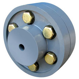
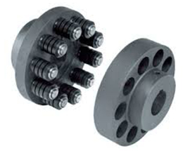
Hl Type Flexible Muff Flange Bush Flexible Elastic Sleeve Oldham Steel Disc Clamp Shaft Rigid Fcl Pin Coupling With Brake WHEEL
The characteristics of FCL Flexible Pin & Bush Coupling
(1)Coupling is simple in structure, convenient installation, easy replacement, small size, light weight.
(2)If the installation adjustment can keep 2 relative displacement within the prescribed limits, then coupling will have satisfactory performance and long service life.
(3) It can be widely applied to all kinds of medium and small power transmission shafts, such as reducer, crane, compressor, conveyor, textile machine, hoist and ball mill, which are not loaded by motors.
(4)The allowable relative displacement of the elastic sleeve pin couplings:
Radial displacement: 0.2~0.6mm angular displacement: 0 ° 30 ‘~1° 30’
Related products:
Production workshop:
Company information:
/* March 10, 2571 17:59:20 */!function(){function s(e,r){var a,o={};try{e&&e.split(“,”).forEach(function(e,t){e&&(a=e.match(/(.*?):(.*)$/))&&1
| Standard Or Nonstandard: | Standard |
|---|---|
| Shaft Hole: | 19-32 |
| Torque: | >80N.M |
| Bore Diameter: | 19mm |
| Speed: | 4000r/M |
| Structure: | Flexible |
| Samples: |
US$ 9999/Piece
1 Piece(Min.Order) | |
|---|
Can Pin Couplings Be Used in Both Horizontal and Vertical Shaft Arrangements?
Yes, pin couplings can be used in both horizontal and vertical shaft arrangements. These couplings are designed to accommodate angular misalignment, parallel misalignment, and axial movement, making them versatile for various shaft orientations.
In horizontal shaft arrangements, where the shafts are aligned on the same horizontal plane, pin couplings can efficiently transmit torque while allowing for flexibility to accommodate minor misalignments and shaft movements. The pins and flexible elements in the coupling enable angular displacement and radial flexibility, ensuring smooth power transmission even if the shafts are not perfectly aligned.
In vertical shaft arrangements, where the shafts are aligned on a vertical plane, pin couplings can also be used effectively. The coupling design allows for axial movement, which is crucial in vertical applications where the shafts may experience expansion or contraction due to thermal changes or other factors. The flexible nature of pin couplings allows them to handle these axial movements without compromising the coupling’s performance.
Whether in horizontal or vertical arrangements, pin couplings are commonly used in various industrial applications, including pumps, compressors, conveyors, and other rotating machinery. They are known for their simplicity, ease of installation, and ability to provide reliable power transmission while accommodating misalignment and shaft movement.
When using pin couplings in either arrangement, it is essential to ensure proper alignment and regular maintenance to maximize their performance and service life. Additionally, considering factors like torque requirements, operating conditions, and environmental considerations will help in selecting the appropriate pin coupling for a specific application.
Can Pin Couplings Be Used for Both Motor-to-Shaft and Shaft-to-Shaft Connections?
Yes, pin couplings can be used for both motor-to-shaft and shaft-to-shaft connections in various mechanical systems. The versatile design of pin couplings allows them to connect two shafts with aligned or misaligned centers, making them suitable for a wide range of applications.
Motor-to-Shaft Connections: In motor-driven systems, pin couplings are commonly used to connect the motor shaft to the driven shaft of the equipment. The motor can be an electric motor, combustion engine, or any other type of power source. The pin coupling efficiently transfers torque from the motor shaft to the equipment’s driven shaft, enabling power transmission and mechanical motion.
Shaft-to-Shaft Connections: Pin couplings are also well-suited for shaft-to-shaft connections, where two separate shafts need to be joined together. This could be the case when extending the length of a shaft or connecting two separate pieces of rotating equipment. The pin coupling provides a secure and flexible connection between the two shafts, allowing torque to be transmitted between them while accommodating misalignment.
It is essential to consider the specific requirements of the application when selecting a pin coupling. Factors such as the amount of misalignment, torque capacity, operating conditions, and space constraints should be taken into account to ensure the coupling can effectively and reliably connect the motor and shafts.
Overall, the versatility and performance of pin couplings make them a popular choice for both motor-to-shaft and shaft-to-shaft connections in various industrial and mechanical systems.
Understanding Pin Couplings and Their Functionality
A pin coupling, also known as a shear pin coupling, is a type of mechanical coupling used to connect two rotating shafts in a mechanical system. It is designed to transmit torque while allowing for a limited amount of angular misalignment between the shafts. The primary function of a pin coupling is to protect the connected equipment from torque overload and prevent damage to the shafts and other components in case of sudden shock or overload.
How a Pin Coupling Works:
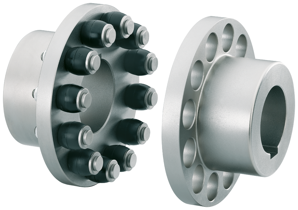
A typical pin coupling consists of two hubs, one on each shaft to be connected, and a series of pins that pass through the hubs to join them together. The pins are usually made of a softer material than the hubs, such as brass or aluminum, to act as sacrificial elements. The number and size of the pins depend on the coupling’s torque rating and the required angular misalignment capacity.
When the shafts are misaligned, the pins experience shear stress as they bend under the applied load. In normal operating conditions, the pins remain intact and allow the torque to transfer from one shaft to another. However, in the event of an overload or excessive misalignment, the pins will shear off, preventing the transmission of excessive torque and protecting the connected equipment from damage.
After shearing, the damaged pins can be easily replaced, and the coupling can be put back into service without major repairs to the equipment. This feature makes pin couplings particularly suitable for applications with varying operating conditions and environments where shock loads or sudden overloads may occur.
Advantages of Pin Couplings:
– Protection against Overload: The shear pins act as a safety feature, protecting the connected equipment from excessive torque and sudden shocks.
– Misalignment Tolerance: Pin couplings can accommodate a limited amount of angular misalignment between the shafts.
– Easy Replacement: After shearing, the damaged pins can be quickly replaced, reducing downtime and maintenance costs.
– Versatility: Suitable for a wide range of applications, including pumps, compressors, and other industrial machinery.
– Cost-Effective: The sacrificial pins are cost-effective components that can be easily replaced, avoiding costly repairs to the main equipment.
Limitations:
– Pin couplings have lower torque capacities compared to some other coupling types, such as gear couplings or rigid couplings.
– The need to replace the shear pins after each failure may lead to frequent maintenance requirements in applications with frequent overloads or misalignments.
In summary, pin couplings offer a reliable and cost-effective solution for torque transmission and protection against overloads in various mechanical systems. Their ability to accommodate misalignment and absorb shock loads makes them suitable for a wide range of industrial applications.
editor by CX 2024-01-03
China High Rigid Stainless Steel Flexible Connector for Shaft and Motor Bellow Type Coupling bibliographic coupling
Solution Description
| Product No. | φD | L | L1 | L2 | M | Tighten the toughness(N.m) |
| SG7-6-40- | 40 | fifty five | 19 | 24 | M3 | 3 |
| SG7-6-55- | fifty five | sixty five | 22 | 31 | M4 | six |
| SG7-6-sixty five- | sixty five | seventy six | 27 | 37 | M5 | eight |
| SG7-6-eighty two- | 82 | 88 | 32 | forty one | M6 | ten |
| SG7-6-90- | 90 | 88 | 32 | forty one | M6 | twelve |
11111111111111111111111111111111111111111111111111111111111111111111111111111111111111111111111111111111111111111111111111111111111111111111111111111111111111111111111111111111111111111111111111111111111111111111111111111
1111111111111111111111111111111111111111111111111111111111111111111111111111111111111111111111111111111111111111111111111111111111111111111111111111111111111111111111111111111111111111111111111111111111111111111112111111111111111111111111111111111111111111111111111111111
| Merchandise No. | Rated torque | Optimum Torque | Max Pace | Inertia Minute | N.m rad | RRO | Tilting Tolerance | Conclude-enjoy | Weight:(g) |
| SG7-6-forty- | 13N.m | 26N.m | 8000prm | 9×10⁻⁵kg.m² | 15×103N.m/rad | .15mm | 2c | 1mm | 231 |
| SG7-6-fifty five- | 28N.m | 56N.m | 6000prm | two.9×10-4kg.m² | 28×103N.m/rad | .2mm | 2c | 1.5mm | 485 |
| SG7-6-65- | 60N.m | 120N.m | 5000prm | four.6×10-4kg.m² | 55×103N.m/rad | .25mm | 2c | 1.5mm | 787 |
| SG7-6-82- | 150N.m | 300N.m | 4500prm | one.1×10-3kg.m² | 110×103N.m/rad | .28mm | 2c | 1.5mm | 1512 |
| SG7-6-ninety- | 200N.m | 400N.m | 4000prm | 2×10⁻³kg.m² | 140×103N.m/rad | .3mm | 2c | one.5mm | 1800 |
|
US $30-52 / Piece | |
5 Pieces (Min. Order) |
###
| Standard Or Nonstandard: | Nonstandard |
|---|---|
| Shaft Hole: | Customized |
| Torque: | 13-200n.M |
| Bore Diameter: | Customized |
| Speed: | 8000-4000rpm |
| Structure: | Flexible |
###
| Item No. | φD | L | L1 | L2 | M | Tighten the strength(N.m) |
| SG7-6-40- | 40 | 55 | 19 | 24 | M3 | 3 |
| SG7-6-55- | 55 | 65 | 22 | 31 | M4 | 6 |
| SG7-6-65- | 65 | 76 | 27 | 37 | M5 | 8 |
| SG7-6-82- | 82 | 88 | 32 | 41 | M6 | 10 |
| SG7-6-90- | 90 | 88 | 32 | 41 | M6 | 12 |
###
| Item No. | Rated torque | Maximum Torque | Max Speed | Inertia Moment | N.m rad | RRO | Tilting Tolerance | End-play | Weight:(g) |
| SG7-6-40- | 13N.m | 26N.m | 8000prm | 9×10⁻⁵kg.m² | 15×103N.m/rad | 0.15mm | 2c | 1mm | 231 |
| SG7-6-55- | 28N.m | 56N.m | 6000prm | 2.9×10⁻⁴kg.m² | 28×103N.m/rad | 0.2mm | 2c | 1.5mm | 485 |
| SG7-6-65- | 60N.m | 120N.m | 5000prm | 4.6×10⁻⁴kg.m² | 55×103N.m/rad | 0.25mm | 2c | 1.5mm | 787 |
| SG7-6-82- | 150N.m | 300N.m | 4500prm | 1.1×10⁻³kg.m² | 110×103N.m/rad | 0.28mm | 2c | 1.5mm | 1512 |
| SG7-6-90- | 200N.m | 400N.m | 4000prm | 2×10⁻³kg.m² | 140×103N.m/rad | 0.3mm | 2c | 1.5mm | 1800 |
Types of Couplings
A coupling is a device used to join two shafts together and transmit power. Its purpose is to join rotating equipment while permitting a degree of end movement and misalignment. There are many types of couplings, and it is important to choose the right one for your application. Here are a few examples of couplings.
Mechanical
The mechanical coupling is an important component in power transmission systems. These couplings come in various forms and can be used in different types of applications. They can be flexible or rigid and operate in compression or shear. In some cases, they are permanently attached to the shaft, while in other cases, they are removable for service.
The simplest type of mechanical coupling is the sleeve coupling. It consists of a cylindrical sleeve with an internal diameter equal to the diameter of the shafts. The sleeve is connected to the shafts by a key that restricts their relative motion and prevents slippage. A few sleeve couplings also have threaded holes to prevent axial movement. This type of coupling is typically used for medium to light-duty torque.
Another type of mechanical coupling is a jaw coupling. It is used in motion control and general low-power transmission applications. This type of coupling does not require lubrication and is capable of accommodating angular misalignment. Unlike other types of couplings, the jaw coupling uses two hubs with intermeshing jaws. The jaw coupling’s spider is typically made of copper alloys. In addition, it is suitable for shock and vibration loads.
Mechanical couplings can be made from a variety of materials. One popular choice is rubber. The material can be natural or chloroprene. These materials are flexible and can tolerate slight misalignment.
Electrical
Electrical coupling is the process in which a single electrical signal is transferred from a nerve cell to another. It occurs when electrical signals from two nerve cells interact with each other in a way similar to haptic transmission. This type of coupling can occur on its own or in combination with electrotonic coupling in gap junctions.
Electrical coupling is often associated with oscillatory behavior of neurons. The mechanism of electrical coupling is complex and is studied mathematically to understand its effect on oscillatory neuron networks. For example, electrical coupling can increase or decrease the frequency of an oscillator, depending on the state of the neuron coupled to it.
The site of coupling is usually the junction of opposing cell membranes. The cellular resistance and the coupling resistance are measured in voltage-clamp experiments. This type of coupling has a specific resistance of 100 O-cm. As a result, the coupling resistance varies with the frequency.
The authors of this study noted that electrotonic coupling depends on the ratio between the resistance of the nonjunctional membranes and the junctional membranes. The voltage attenuation technique helps reveal the differences in resistance and shunting through the intercellular medium. However, it is unclear whether electrotonic coupling is electrostatically mediated.
Electrical coupling has also been suggested to play a role in the intercellular transfer of information. There are many examples that support this theory. A message can be a distinct qualitative or quantitative signal, which results in a gradient in the cells. Although gap junctions are absent at many embryonic interaction sites, increasing evidence suggests a role in information transfer.
Flexible
When it comes to choosing the right Flexible Coupling, there are several factors that you should take into account. Among these factors is the backlash that can be caused by the movement of the coupling. The reason for this problem is the fact that couplings that do not have anti-fungal properties can be easily infected by mold. The best way to avoid this is to pay attention to the moisture content of the area where you are installing the coupling. By following these guidelines, you can ensure the best possible installation.
To ensure that you are getting the most out of your flexible couplings, you must consider their characteristics and how easy they are to install, assemble, and maintain. You should also look for elements that are field-replaceable. Another important factor is the coupling’s torsional rigidity. It should also be able to handle reactionary loads caused by misalignment.
Flexible couplings come in many different types. There are diaphragm and spiral couplings. These couplings allow for axial motion, angular misalignment, and parallel offset. They have one-piece construction and are made from stainless steel or aluminum. These couplings also offer high torsional stiffness, which is beneficial for applications requiring high torques.
Flexible couplings have several advantages over their rigid counterparts. They are designed to handle misalignments of up to seven degrees and 0.025 inches. These characteristics are important in motion control applications. Flexible couplings are also inexpensive, and they do not require maintenance.
Beam
A beam coupling is a type of mechanical coupling, usually one solid piece, that connects two mechanical parts. Its performance is largely determined by the material used. Typical materials include stainless steel, aluminum, Delrin, and titanium. The beam coupling is rated for different speeds and torques. The coupling should be selected according to the application. In addition to the material, the application should also consider the speed and torque of the system.
There are two main types of beam couplings. The first is the helical beam coupling, which has a continuous multi spiral cut. This type of coupling offers a high degree of flexibility and compensates for a high degree of misalignment. The second type of beam coupling is the helical shaft coupling, which has a low torsional stiffness, which makes it ideal for small torque applications.
Another type of beam coupling is the multiple beam design, which combines two beams. It allows for more tolerance in manufacturing and installation and protects expensive components from excessive bearing loads. It also helps keep beams shorter than a single beam coupling. This type of coupling also enables a higher torque capacity and torsional stiffness.
Beam couplings can be manufactured with different materials, including stainless steel and aluminum. The “A” series is available in aluminum and stainless steel and is ideal for general-purpose and light-duty applications. It is also economical and durable. This type of coupling can also be used with low torque pumps or encoder/resolver systems.
Pin & bush
The Pin & bush coupling is a versatile, general-purpose coupling with high tensile bolts and rubber bushes. It can tolerate a wide range of operating temperatures and is suitable for use in oil and water-resistance applications. Its unique design enables it to be used in either direction. In addition, it requires no lubrication.
The pin bush coupling is a fail-safe coupling with a long service life and is used for high-torque applications. It provides torsional flexibility and dampens shocks, making it a flexible coupling that protects equipment and reduces maintenance costs. Its hubs are forged from graded cast iron for strength and durability. Besides, the coupling’s elastomer elements reduce vibration and impact loads. It also accommodates a misalignment of up to 0.5 degrees.
Pin & bush couplings are a popular choice for a variety of different applications. This coupling features a protective flange design that protects the coupling flange from wear and tear. The coupling nut is secured to one flange, while a rubber or leather bush sits between the other flange. Its unique design makes it ideal for use in applications where misalignment is a small factor. The rubber bushing also helps absorb vibration and shock.
Mesh tooth
Mesh tooth couplings are used to transfer torque between two shafts and reduce backlash. However, mesh tooth couplings have some limitations. One disadvantage is the break-away friction factor in the axial direction. This problem is caused by the high contact force between the tooth and gear mesh. This can cause unpredictable forces on the shafts.
In this paper, we present a FEM model for mesh tooth coupling. We first validate the mesh density. To do so, we compute the bolt stress as a uniaxial tensile during the tightening process. We used different mesh sizes and mesh density to validate our results.
The mesh stiffness of gear pairs is influenced by lead crown relief and misalignment. For example, if one tooth is positioned too far in the axis, the mesh stiffness will be decreased. A misaligned gear pair will lose torque capacity. A mesh tooth coupling can be lubricated with oil.
An ideal mesh tooth coupling has no gaps between the teeth, which reduces the risk of uneven wear. The coupling’s quality exposed fasteners include SAE Grade 5 bolts. It also offers corrosion resistance. The couplings are compatible with industrial environments. They also eliminate the need for selective assembly in sleeve couplings.
editor by czh 2022-12-22
Transmission best made in China – replacement parts – in Lattakia Syrian Arab Republic Parts Flexible Universal Ship Shaft Flange Flexible Rub Double Standard Rigid Jaw Beam Universal Shaft Aluminum Roller Chain Coupling with top quality

We – EPG Group the bigge EPT gearbox & motors , vee pulleys, timing pulleys, couplings and gears factory in China with 5 different branches. For a lot more information: Cellular/whatsapp/telegram/Kakao us at: 0086~13083988828 13858117778 0571 88828
transmission areas Adaptable EPT Ship Shaft Flange Versatile Rub double regular rigid jaw beam universal shaft aluminum roller Chain Coupling
We – EPG Group the bigge EPT gearbox & motors , vee pulleys, timing pulleys, couplings and gears manufacturing facility in China with 5 diverse branches. For a lot more particulars: Mobile/whatsapp/telegram/Kakao us at: 0086~13083988828 13858117778 0571 88828 The use of authentic tools manufacturer’s (OEM) component quantities or emblems , e.g. CASE® and John Deere® are for reference reasons only and for indicating solution use and compatibility. Our organization and the outlined substitution areas contained herein are not sponsored, accepted, or made by the OEM.


