Category Archives: shear pin coupling

China Standard Stainless Steel Quick CZPT Camlock Type D F Type C for Hose Fitting Crimp Camlock with Hot selling

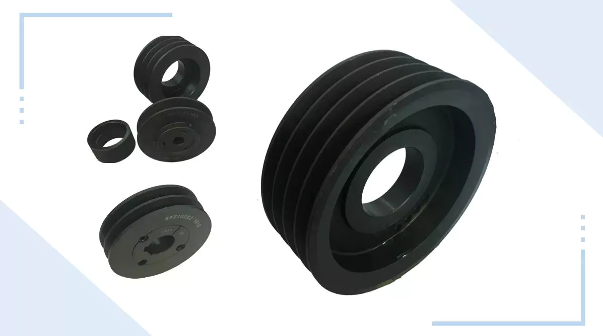
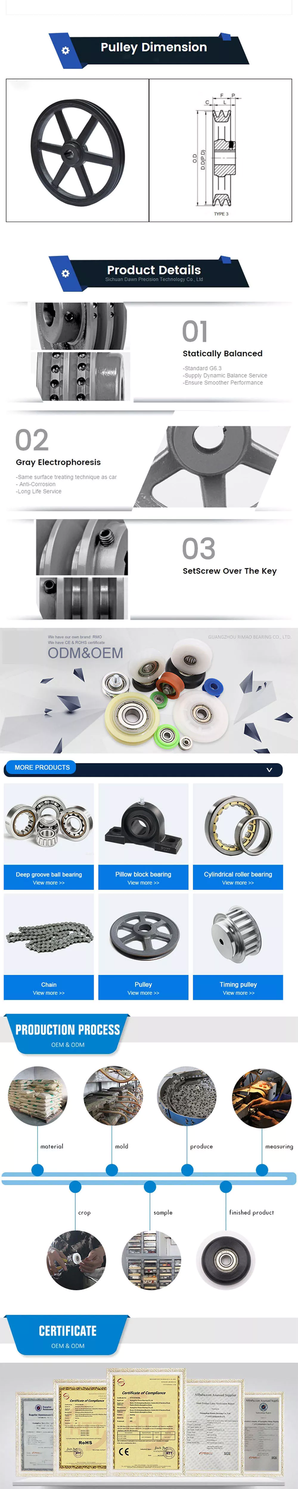
Merchandise Description

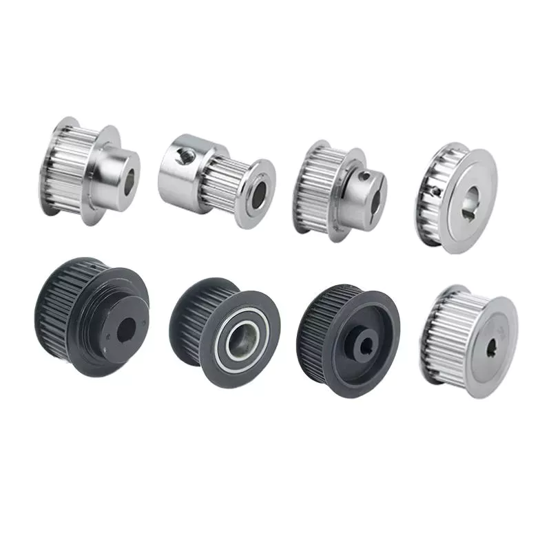
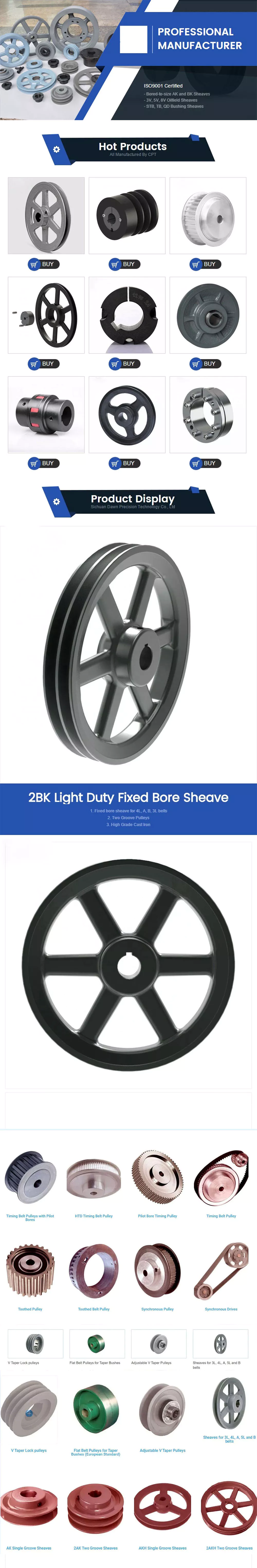
Solution Description
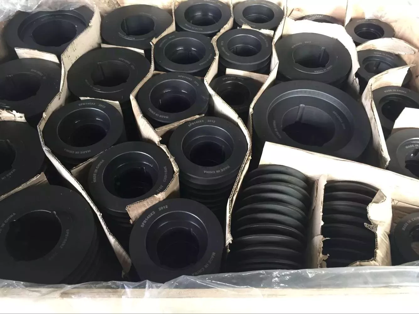
Business Profile

The Pipeline of Cheng-jiu,
Link the Globe, Join You and Me


Method Flow

Certifications


Screw Shaft Features Explained

When choosing the screw shaft for your application, you should consider the features of the screws: threads, lead, pitch, helix angle, and more. You may be wondering what these features mean and how they affect the screw’s performance. This article explains the differences between these factors. The following are the features that affect the performance of screws and their properties. You can use these to make an informed decision and purchase the right screw. You can learn more about these features by reading the following articles.

Threads

The major diameter of a screw thread is the larger of the two extreme diameters. The major diameter of a screw is also known as the outside diameter. This dimension can’t be directly measured, but can be determined by measuring the distance between adjacent sides of the thread. In addition, the mean area of a screw thread is known as the pitch. The diameter of the thread and pitch line are directly proportional to the overall size of the screw.
The threads are classified by the diameter and pitch. The major diameter of a screw shaft has the largest number of threads; the smaller diameter is called the minor diameter. The thread angle, also known as the helix angle, is measured perpendicular to the axis of the screw. The major diameter is the largest part of the screw; the minor diameter is the lower end of the screw. The thread angle is the half distance between the major and minor diameters. The minor diameter is the outer surface of the screw, while the top surface corresponds to the major diameter.
The pitch is measured at the crest of a thread. In other words, a 16-pitch thread has a diameter of one sixteenth of the screw shaft’s diameter. The actual diameter is 0.03125 inches. Moreover, a large number of manufacturers use this measurement to determine the thread pitch. The pitch diameter is a critical factor in successful mating of male and female threads. So, when determining the pitch diameter, you need to check the thread pitch plate of a screw.
screwshaft

Lead

In screw shaft applications, a solid, corrosion-resistant material is an important requirement. Lead screws are a robust choice, which ensure shaft direction accuracy. This material is widely used in lathes and measuring instruments. They have black oxide coatings and are suited for environments where rusting is not acceptable. These screws are also relatively inexpensive. Here are some advantages of lead screws. They are highly durable, cost-effective, and offer high reliability.
A lead screw system may have multiple starts, or threads that run parallel to each other. The lead is the distance the nut travels along the shaft during a single revolution. The smaller the lead, the tighter the thread. The lead can also be expressed as the pitch, which is the distance between adjacent thread crests or troughs. A lead screw has a smaller pitch than a nut, and the smaller the lead, the greater its linear speed.
When choosing lead screws, the critical speed is the maximum number of revolutions per minute. This is determined by the minor diameter of the shaft and its length. The critical speed should never be exceeded or the lead will become distorted or cracked. The recommended operational speed is around eighty percent of the evaluated critical speed. Moreover, the lead screw must be properly aligned to avoid excessive vibrations. In addition, the screw pitch must be within the design tolerance of the shaft.

Pitch

The pitch of a screw shaft can be viewed as the distance between the crest of a thread and the surface where the threads meet. In mathematics, the pitch is equivalent to the length of one wavelength. The pitch of a screw shaft also relates to the diameter of the threads. In the following, the pitch of a screw is explained. It is important to note that the pitch of a screw is not a metric measurement. In the following, we will define the two terms and discuss how they relate to one another.
A screw’s pitch is not the same in all countries. The United Kingdom, Canada, and the United States have standardized screw threads according to the UN system. Therefore, there is a need to specify the pitch of a screw shaft when a screw is being manufactured. The standardization of pitch and diameter has also reduced the cost of screw manufacturing. Nevertheless, screw threads are still expensive. The United Kingdom, Canada, and the United States have introduced a system for the calculation of screw pitch.
The pitch of a lead screw is the same as that of a lead screw. The diameter is 0.25 inches and the circumference is 0.79 inches. When calculating the mechanical advantage of a screw, divide the diameter by its pitch. The larger the pitch, the more threads the screw has, increasing its critical speed and stiffness. The pitch of a screw shaft is also proportional to the number of starts in the shaft.

Helix angle

The helix angle of a screw shaft is the angle formed between the circumference of the cylinder and its helix. Both of these angles must be equal to 90 degrees. The larger the lead angle, the smaller the helix angle. Some reference materials refer to angle B as the helix angle. However, the actual angle is derived from calculating the screw geometry. Read on for more information. Listed below are some of the differences between helix angles and lead angles.
High helix screws have a long lead. This length reduces the number of effective turns of the screw. Because of this, fine pitch screws are usually used for small movements. A typical example is a 16-mm x 5-inch screw. Another example of a fine pitch screw is a 12x2mm screw. It is used for small moves. This type of screw has a lower lead angle than a high-helix screw.
A screw’s helix angle refers to the relative angle of the flight of the helix to the plane of the screw axis. While screw helix angles are not often altered from the standard square pitch, they can have an effect on processing. Changing the helix angle is more common in two-stage screws, special mixing screws, and metering screws. When a screw is designed for this function, it should be able to handle the materials it is made of.
screwshaft

Size

The diameter of a screw is its diameter, measured from the head to the shaft. Screw diameters are standardized by the American Society of Mechanical Engineers. The diameters of screws range from 3/50 inches to sixteen inches, and more recently, fractions of an inch have been added. However, shaft diameters may vary depending on the job, so it is important to know the right size for the job. The size chart below shows the common sizes for screws.
Screws are generally referred to by their gauge, which is the major diameter. Screws with a major diameter less than a quarter of an inch are usually labeled as #0 to #14 and larger screws are labeled as sizes in fractions of an inch. There are also decimal equivalents of each screw size. These measurements will help you choose the correct size for your project. The screws with the smaller diameters were not tested.
In the previous section, we described the different shaft sizes and their specifications. These screw sizes are usually indicated by fractions of an inch, followed by a number of threads per inch. For example, a ten-inch screw has a shaft size of 2” with a thread pitch of 1/4″, and it has a diameter of two inches. This screw is welded to a two-inch Sch. 40 pipe. Alternatively, it can be welded to a 9-inch O.A.L. pipe.
screwshaft

Shape

Screws come in a wide variety of sizes and shapes, from the size of a quarter to the diameter of a U.S. quarter. Screws’ main function is to hold objects together and to translate torque into linear force. The shape of a screw shaft, if it is round, is the primary characteristic used to define its use. The following chart shows how the screw shaft differs from a quarter:
The shape of a screw shaft is determined by two features: its major diameter, or distance from the outer edge of the thread on one side to the inner smooth surface of the shaft. These are generally two to sixteen millimeters in diameter. Screw shafts can have either a fully threaded shank or a half-threaded shank, with the latter providing better stability. Regardless of whether the screw shaft is round or domed, it is important to understand the different characteristics of a screw before attempting to install it into a project.
The screw shaft’s diameter is also important to its application. The ball circle diameter refers to the distance between the center of two opposite balls in contact with the grooves. The root diameter, on the other hand, refers to the distance between the bottommost grooves of the screw shaft. These are the two main measurements that define the screw’s overall size. Pitch and nominal diameter are important measurements for a screw’s performance in a particular application.

Lubrication

In most cases, lubrication of a screw shaft is accomplished with grease. Grease is made up of mineral or synthetic oil, thickening agent, and additives. The thickening agent can be a variety of different substances, including lithium, bentonite, aluminum, and barium complexes. A common classification for lubricating grease is NLGI Grade. While this may not be necessary when specifying the type of grease to use for a particular application, it is a useful qualitative measure.
When selecting a lubricant for a screw shaft, the operating temperature and the speed of the shaft determine the type of oil to use. Too much oil can result in heat buildup, while too little can lead to excessive wear and friction. The proper lubrication of a screw shaft directly affects the temperature rise of a ball screw, and the life of the assembly. To ensure the proper lubrication, follow the guidelines below.
Ideally, a low lubrication level is appropriate for medium-sized feed stuff factories. High lubrication level is appropriate for larger feed stuff factories. However, in low-speed applications, the lubrication level should be sufficiently high to ensure that the screws run freely. This is the only way to reduce friction and ensure the longest life possible. Lubrication of screw shafts is an important consideration for any screw.

China Drive Coupling

By using drive couplings a connection is made between the driving element such as an electromotor, and the pump. Drive couplings also known as shaft couplings are often used in combination with a bell housing. Findynamica has a complete range of drive couplings for powers ranging from 0,18 to 132 kW available from stock.

HRC couplings consist of 2 halves with a star-shaped rubber unit in the centre. This is an excellent all-round coupling which is CZPT to adapt to some imbalances.

The HRC couplings are available pilot bored and bored for taperlock bushes in order to allow maximum flexibility in the choice of shaft diameters. The HRC couplings can be used at temperatures from -40 degrees to +100 degrees.

HRC couplings are easy to use and are stocked bored for taperlock bushes. As a result, they are easy to install and remove. In case of breakdowns, a new coupling can be installed quickly as it does not have to be bored to dimensions. You only have to choose the taperlock bushes for the shaft diameters on which to install the coupling.

HRC couplings are used in industry in all situations where 2 shafts are to be connected.

Worm Shafts and Gearboxes

If you have a gearbox, you may be wondering what the best Worm Shaft is for your application. There are several things to consider, including the Concave shape, Number of threads, and Lubrication. This article will explain each factor and help you choose the right Worm Shaft for your gearbox. There are many options available on the market, so don’t hesitate to shop around. If you are new to the world of gearboxes, read on to learn more about this popular type of gearbox.
worm shaft

Concave shape

The geometry of a worm gear varies considerably depending on its manufacturer and its intended use. Early worms had a basic profile that resembled a screw thread and could be chased on a lathe. Later, tools with a straight sided g-angle were developed to produce threads that were parallel to the worm’s axis. Grinding was also developed to improve the finish of worm threads and minimize distortions that occur with hardening.
To select a worm with the proper geometry, the diameter of the worm gear must be in the same unit as the worm’s shaft. Once the basic profile of the worm gear is determined, the worm gear teeth can be specified. The calculation also involves an angle for the worm shaft to prevent it from overheating. The angle of the worm shaft should be as close to the vertical axis as possible.
Double-enveloping worm gears, on the other hand, do not have a throat around the worm. They are helical gears with a straight worm shaft. Since the teeth of the worm are in contact with each other, they produce significant friction. Unlike double-enveloping worm gears, non-throated worm gears are more compact and can handle smaller loads. They are also easy to manufacture.
The worm gears of different manufacturers offer many advantages. For instance, worm gears are 1 of the most efficient ways to increase torque, while lower-quality materials like bronze are difficult to lubricate. Worm gears also have a low failure rate because they allow for considerable leeway in the design process. Despite the differences between the 2 standards, the overall performance of a worm gear system is the same.
The cone-shaped worm is another type. This is a technological scheme that combines a straight worm shaft with a concave arc. The concave arc is also a useful utility model. Worms with this shape have more than 3 contacts at the same time, which means they can reduce a large diameter without excessive wear. It is also a relatively low-cost model.
worm shaft

Thread pattern

A good worm gear requires a perfect thread pattern. There are a few key parameters that determine how good a thread pattern is. Firstly, the threading pattern must be ACME-threaded. If this is not possible, the thread must be made with straight sides. Then, the linear pitch of the “worm” must be the same as the circular pitch of the corresponding worm wheel. In simple terms, this means the pitch of the “worm” is the same as the circular pitch of the worm wheel. A quick-change gearbox is usually used with this type of worm gear. Alternatively, lead-screw change gears are used instead of a quick-change gear box. The pitch of a worm gear equals the helix angle of a screw.
A worm gear’s axial pitch must match the circular pitch of a gear with a higher axial pitch. The circular pitch is the distance between the points of teeth on the worm, while the axial pitch is the distance between the worm’s teeth. Another factor is the worm’s lead angle. The angle between the pitch cylinder and worm shaft is called its lead angle, and the higher the lead angle, the greater the efficiency of a gear.
Worm gear tooth geometry varies depending on the manufacturer and intended use. In early worms, threading resembled the thread on a screw, and was easily chased using a lathe. Later, grinding improved worm thread finishes and minimized distortions from hardening. As a result, today, most worm gears have a thread pattern corresponding to their size. When selecting a worm gear, make sure to check for the number of threads before purchasing it.
A worm gear’s threading is crucial in its operation. Worm teeth are typically cylindrical, and are arranged in a pattern similar to screw or nut threads. Worm teeth are often formed on an axis of perpendicular compared to their parallel counterparts. Because of this, they have greater torque than their spur gear counterparts. Moreover, the gearing has a low output speed and high torque.

Number of threads

Different types of worm gears use different numbers of threads on their planetary gears. A single threaded worm gear should not be used with a double-threaded worm. A single-threaded worm gear should be used with a single-threaded worm. Single-threaded worms are more effective for speed reduction than double-threaded 1s.
The number of threads on a worm’s shaft is a ratio that compares the pitch diameter and number of teeth. In general, worms have 1,2,4 threads, but some have 3, 5, or 6. Counting thread starts can help you determine the number of threads on a worm. A single-threaded worm has fewer threads than a multiple-threaded worm, but a multi-threaded worm will have more threads than a mono-threaded planetary gear.
To measure the number of threads on a worm shaft, a small fixture with 2 ground faces is used. The worm must be removed from its housing so that the finished thread area can be inspected. After identifying the number of threads, simple measurements of the worm’s outside diameter and thread depth are taken. Once the worm has been accounted for, a cast of the tooth space is made using epoxy material. The casting is moulded between the 2 tooth flanks. The V-block fixture rests against the outside diameter of the worm.
The circular pitch of a worm and its axial pitch must match the circular pitch of a larger gear. The axial pitch of a worm is the distance between the points of the teeth on a worm’s pitch diameter. The lead of a thread is the distance a thread travels in 1 revolution. The lead angle is the tangent to the helix of a thread on a cylinder.
The worm gear’s speed transmission ratio is based on the number of threads. A worm gear with a high ratio can be easily reduced in 1 step by using a set of worm gears. However, a multi-thread worm will have more than 2 threads. The worm gear is also more efficient than single-threaded gears. And a worm gear with a high ratio will allow the motor to be used in a variety of applications.
worm shaft

Lubrication

The lubrication of a worm gear is particularly challenging, due to its friction and high sliding contact force. Fortunately, there are several options for lubricants, such as compounded oils. Compounded oils are mineral-based lubricants formulated with 10 percent or more fatty acid, rust and oxidation inhibitors, and other additives. This combination results in improved lubricity, reduced friction, and lower sliding wear.
When choosing a lubricant for a worm shaft, make sure the product’s viscosity is right for the type of gearing used. A low viscosity will make the gearbox difficult to actuate and rotate. Worm gears also undergo a greater sliding motion than rolling motion, so grease must be able to migrate evenly throughout the gearbox. Repeated sliding motions will push the grease away from the contact zone.
Another consideration is the backlash of the gears. Worm gears have high gear ratios, sometimes 300:1. This is important for power applications, but is at the same time inefficient. Worm gears can generate heat during the sliding motion, so a high-quality lubricant is essential. This type of lubricant will reduce heat and ensure optimal performance. The following tips will help you choose the right lubricant for your worm gear.
In low-speed applications, a grease lubricant may be sufficient. In higher-speed applications, it’s best to apply a synthetic lubricant to prevent premature failure and tooth wear. In both cases, lubricant choice depends on the tangential and rotational speed. It is important to follow manufacturer’s guidelines regarding the choice of lubricant. But remember that lubricant choice is not an easy task.

China Reducer Coupling

EPT has a comprehensive line of sewer and drain fittings include valves, couplings, and connectors in PVC and styrene. Diverter & Backwater Valves are manufactured from PVC or ABS, our Diverter & Backwater Valves are durable and easy to install and replace. Controls flow to up to 3 septic tank leach fields. Protects low areas from street sewers backflow. Solvent Weld Fittings include tees, elbows, adapters, repair couplings, and reducer couplings manufactured from durable PVC and Styrene. Securely connects sewer and drain pipes. Flexible Couplings are manufactured from black PVC with bactericides and fungicides added for extra protection. Clamps are stainless steel. Quickly connects sewer, drain, waste and vent piping in any pipe material. Connectors and O-Rings install easily and quickly to provide leak-proof seals. Seals connections between most types of sockets, hubs, bells and spigots. Quickly connects 4″ house pipe and 6″ sewer pipe.

Types of pulleys and their advantages and disadvantages

There are several types of pulleys. Learn the basic equations of the pulley system. Then learn about the different uses for pulleys. The disadvantages of using pulleys will be covered. Knowing these, you can buy the pulley that suits your needs. Here are some of the best pulley types and their pros and cons.
pulley

Basic equations of pulley systems

A pulley system is a mechanism that allows 2 blocks of a certain mass to be connected by a taut rope. The acceleration of each block is the same in magnitude and direction. The external force acting on each block is the weight of the block (10g) and the 10sion in the string. The 10sion between the 2 blocks is the total 10sion and the force acting on the pulley is the weight of the 2 blocks.
This simple mechanism uses 2 simple equations to explain how the system works. First, the mass of the weight on both sides of the pulley must be the same. When the weight is forced to move, the rope tightens and the second pulley descends. The weight is also attached to the second pulley and must be the same distance as the first pulley. This will result in a speed ratio of 2 times the distance covered by the first pulley.
Second, we have to calculate the force required to lift the object. The lower mass is supported by a wire configuration passing through all pulleys, while the uppermost pulley is used to apply the force. The lower block is used to support the weight. The applied force needs to travel a distance nx to move the weight. This distance, called MA, can be written as:
Once we have gathered the necessary information, we can apply the calculations to the pulley system. We can also use the Mechanical Advantage Calculator to calculate the force on the anchor. To do this, we must apply a force to the load as well as to the pulley itself. Using this equation, we can calculate the force required by the load to lift the load.
pulley

Types of pulleys

There are 3 basic types of pulleys: movable, fixed and compound. Both types of pulleys translate the force applied to them. The ideal mechanical advantage of pulleys is 2. This is because a single movable pulley only doubles the force, whereas a compound pulley doubles or triples the force. This type of pulley is often used with other types of pulleys.
Movable pulls move with the weight of the load, and the force pulling them increases on the lift side. They are often found in utility elevators and construction cranes. These systems are very simple, inexpensive and quiet to use. The force required to lift the object depends on the mechanical advantage of the system. The 2 most common types of pulleys are listed below. Let’s take a closer look at each 1.
V-shaped pulleys are used in vehicles and electric motors. These pulleys require a “V” belt to function properly. Some have multiple “V” grooves to avoid slipping. They are used in heavy duty applications to reduce the risk of power slip. These pulleys also have more than 1 “V” groove. V-belt pulleys are commonly used in vehicles and electric motors.
Composite pulleys are made from more than 1 type of cable or rope wrapped around the wheel. They can be fixed or hinged and are usually made of stainless steel or bronze. Composite pulleys have multiple layers and can be a single unit or many different components. There are 3 main types of pulleys: fixed pulleys and composite pulleys. These are the most common types. Almost every type of pulley is used for some type of application.
Fixed pulleys have 1 advantage over movable pulleys: they change direction as the weight of the load increases. They are typically used in heavy construction equipment. Gun tackles, patio tackles, and stationary tackles are examples of equipment that use a pulley mechanism. These devices are very common and can be found on most modern construction sites. They provide great convenience for lifting large loads.

application

What are the applications of pulleys? Simply put, a pulley is a mechanical device that transforms a difficult task into an easier 1. It consists of ropes and pulleys. It is usually used to lift objects. Usually, people wrap a rope around a pulley and pull up to lift the object. One disadvantage of using pulleys is that they require the same force as lifting the object directly.
One of the most popular applications of pulleys is lifting heavy objects. They help people pull up heavy objects and blocks. The system can also be used in seeders, lifts, grinders, etc. Other applications include raising flags, loading cargo, pulling curtains and rock or mountain climbing. Students can learn about the various uses of pulleys and the physics behind them.
Pulleys can be made of many different materials, depending on the application. Some are movable, which means they move with the object they are used to lift. This pulley system can be made of nylon, wire rope or fiber material. The best part about these systems is that they are easy to install and maintain. For a better grasp, use the guide or video tutorial to learn more about the pulley system and how it works.
Tapered pulleys are common in paper mills. They are high-quality pulleys that transmit power to connected parts. They can be dynamic or static and have different balances. Because pulley systems are highly customized, most industrial applications require systems designed specifically for specific applications. In this way, the system is safe, simple and inexpensive. The benefits of this design are endless.
The most common use of pulleys is for motor drives. They are used to minimize noise by applying force to the shaft to reduce the workload. They are also less expensive than gears and do not require lubrication. Furthermore, they can change the direction of the applied force. They are also less expensive than gears and are often used with other components. A screw is a cylindrical member with helical ribs used to connect something.
pulley

shortcoming

Although the pulley system makes it easier to move heavy objects, it still has some drawbacks. When using a pulley system, you must remember that the force required to lift the weight increases with the number of cycles. In addition, the distance between the puller and the heavy object increases, which may lead to accidents. Also, moving heavy objects can be tricky if the rope slips. Pulley systems are not very expensive and can be easily assembled. However, it does require a lot of space.
First, it is not efficient. Besides being inefficient, pulleys produce different forces at different speeds. Fixed pulleys use more force than the load, while movable pulleys move with the load. A movable pulley requires less force than a fixed pulley, but the combined system travels a long distance. Therefore, this method is not as efficient as the fixed method.
Pulleys are not only used in industrial processes. You can see them in various places in your daily life. For example, large construction cranes use pulleys to lift heavy loads. Even flagpoles, blinds, clotheslines, ziplines, motors and climbing equipment use pulleys. Still, despite their advantages, the disadvantages are not too serious.
Another disadvantage of the pulley is its wear and tear. While a pulley’s housing is theoretically infinite, its bearings and locking components typically wear out over time. To overcome this problem, a new bearing and locking assembly can be installed. No need to replace the housing and shaft, the entire assembly can be re-bonded and painted to replicate the original look. Alternatively, the pulley can be replaced with a new housing and shaft.
Using pulleys can also reduce the advantage of pulleys. On the other hand, interception and tackle is a system in which 2 pulleys are connected to each other using ropes. Unlike pulleys, pulley pulley systems can be adjusted in the direction of travel and can move heavy loads up to 4 times their force when used in hydraulic lifts.

China factory Worm Reducer For Paper Cutting Machine with high quality

Type C.D.(mm) Ratio Input power(kw) Input speed(r/min) Transmission fficiency(%) Allowed working oil temperature(℃)
10TU100 100 40 3 1680 80 10~100
Type C.D.(mm) Ratio Input power(kw) Input speed(r/min) Transmission fficiency(%) Allowed working oil temperature(℃)
T109 125 40 4 1680 80 10~100

China Professional 4535 Taper Lock Bushings with Best Sales

4535 Taper Lock Bushings

If you might be in the market for a new bushing for your motor, you may possibly be pondering: “What is a tapered bushing?” If so, you’ve come to the proper location. This article will support you realize the big difference among Standard Taper Bushings and Taper-Lock Bushings, and the distinctions between them. No subject which variety of bushing you decide on, you will uncover a tapered lock bushing that suits your motor.
Break up Taper Bushings, also recognized as QDs, are created to mount sprockets, and pulleys to shafts. They are divided alongside their outer diameter and keyed to the travel parts, guaranteeing that the elements are securely mounted on the shaft even if the fasteners crack. Split tapered bushings are interchangeable amongst makers, so you never have to fret about figuring out what kind of bushing you need primarily based on its look.
A tapered bushing is a locking system generally utilized in energy transmission components. They are made of precision solid iron and computer etched to specify their dimensions. These bushings characteristic wedge action handles for a safe link and outstanding clamping drive. The most typical kinds of tapered bushings are QD bushings and Taper-Lock bushings. Generally, they are employed in programs requiring large torque.
An additional tapered bushing is the QTL Tapered Lock Clamp Bushing. These bushings are designed to clamp the hub securely to the axle. They offer greater alignment and are much more precise than keyways. To put in a taper lock bushing, you must purchase the suitable QTL taper lock flange and hub. This makes certain a tight suit. This is comparable to a shrink-match since the 2 bushings do not transfer after put in.

Taper Lock Bushing Measurement Chart

The dimension table underneath displays the regular dimensions of the taper lock bushing, please note that the subsequent determine is the standard dimension essential, the actual set up and removing of the bolt holes may differ.

A single of the numerous rewards of tapered locking bushing is its capacity to minimize its complete size. This special design and style of the bushing enables it to match tightly in restricted areas although offering a slimmer in shape than flanged bushings. Nevertheless, when making use of these bushings, it is essential to keep in mind that the interior and outer surfaces of the bushing must be cleaned prior to assembly. In any other case, you will find by yourself changing bushings often.
Always verify bolt dimension just before putting in tapered locking bushings. The dimension chart below displays the regular dimensions of these bushings. These dimensions are for fundamental sizing specifications only, as genuine bolt holes might vary from these on the chart. The lubricant you use is essential to the daily life of your new bushing. No matter of the sort of thread, it is essential to use the proper thread to preserve your automobile in good functioning get.
The variety of holes on the tapered lock bushing will decide its quality and overall performance. An even amount of holes is ideal for large-speed use, whilst a tapered sleeve with an odd quantity of holes is better for minimal-velocity use. Some CBC shops offer these prepared-manufactured bushings in different measurements. If you can’t locate the correct size, you can also search for companies that focus in customized measurements.
Ahead of setting up the tapered lock bushing, you need to extensively cleanse the inside and outdoors of the portion. Remove the previous bushing from the hub. Make sure it has no cracks and traces up with the 50 percent hole. Match threads and holes to guarantee suitable installation. When carried out, set up the new lock bushing into the hub. Then, use a torque wrench to tighten the screws to the advisable torque.

Click and verify out much more products you happen to be hunting for.

Q1. Are you a factory?
A. Yes. We are a manufacturing facility with far more than fifteen many years of producing encounter.

Q2. Is OEM and ODM service accessible?

A. Of course. We have a lot of many years of expertise in OEM&amp ODM support.

Q3. I am acquiring from an additional provider, but need better service. Would you match or defeat the price I am having to pay?
A. We always come to feel we offer the ideal provider and competitive rates. We would be pleased to personalize a aggressive estimate for you, email us.

Further info

Edited

CX

ep

January 18, 2021

Common Description
Consisting of the stress balanced gear pump, DC motor, multi-functional manifold, valves, tank, ect., this power unit is created to operate materials dealing with gear. The lowering motion is achived from the solenoid valve together with the lowering pace controlled by an adjustable needle valve. The left and proper functions are equipped having a dual pilot operated check out valve and cross-over relief valves.
Remark: Please seek advice from our revenue engineer for your diverse pump displacement, motor energy or tank capacity.
Particular Notes
one. This power unit is of S3 duty cycle, i.e.,non-continuous operation,thirty seconds on and 270 seconds off.
2. Clean all of the hydraulic elements concerned in advance of set up of the power unit.
3. Viscosity from the hydraulic oil shoud be 15~46 cst, which really should also be clean and free of impurities.N46 hydraulic oil is advised.
four. This power unit should be mounted horizontal.
five. Check the oil degree from the tank immediately after the primary start out in the energy unit.
6. Oil changing is required following the first a hundred operation hrs, afterwards when every 3000 hours.

ep

January 18, 2021

DUMP TRAILER Energy UNIT- SINGLE ACTING
Standard Description
This electrical power unit has a power up gravity down circuit. Start the motor to lengthen the cylinder and activate the solenoid valve to retract the circuit. Manual override to solenoid valve is usually offered if essential. Also a pressure compen sated movement manage can be extra towards the circuit to regulate the descent speed of the cylinder.
Remark: Please talk to our income engineer for your diverse pump displacement, motor electrical power or tank capacity.
Exclusive Notes
1. This electrical power unit is of S3 duty cycle, i.e., non-continuous operation, 30 seconds on and 270 seconds off.
2. Clean all the hydraulic components concerned in advance of installation of the power unit.
three. Viscosity in the hydraulic oil shoud be 15~46 cst,which need to also be clean and absolutely free of impurities.N46 hydraulic oil is advisable.
four. The power unit ought to be mounted horizontally.
five. Check the oil degree from the tank following the original operating with the energy unit.
six. Oil transforming is required just after the preliminary one hundred operation hours, afterwards as soon as each and every 3000 hours.

DUMP TRAILER Energy UNIT-DOUBLE ACTING
Basic Description
This power unit has a electrical power up power down circuit with load holding on both A & B ports. A stress compensatred flow management is usually extra to circuit to manage the decent speed on the cylinder.
Specific Notes
one. This energy unit is of S3 duty cycle, i.e., non-continuous operation, thirty seconds on and 270 seconds off.
two. Clean the many hydraulic parts concerned before set up of the energy unit.
three. Viscosity in the hydraulic oil shoud be 15~46 cst, which ought to also be clean and no cost of impurities. N46 hydraulic oil is proposed.
4. The electrical power unit need to be mounted horizontally.
5. Check the oil level from the tank after the first operating of the power unit.
6. Oil changing is required just after the preliminary a hundred operation hours, afterwards after every 3000 hrs.

ep

January 18, 2021

Basic Description
Equipped with all the zero leak bidirectional checking sole-noid valves, this energy unit is intended to the 
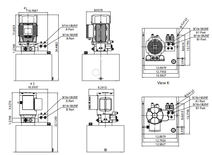
operation of two independent circuits. Which are respectively for the principal and subordinate platforms in the double scissors lift. Two cut-off valves are employed for reducing the machine manually in situation of power loss. If additional independent circuits are demanded to your application please get in touch with us for availability.
Remark: 1. Please seek advice from our revenue engineer to the different pump displacement, motor electrical power or tank capability.
2. CSA or UL certified motors can be found upon request.
Unique Notes
one. The AC motor is of S3 duty cycle, which might only function intermittently and repeatedly, i.e., 1minute on and 9 minutes off.
2. Clean the many hydraulic parts concerned just before set up of the electrical power unit.
3. Viscosity with the oil shoud be 15~46 cst,as well as the oil should really be clean and totally free of impurities,N46 hydraulic oil is encouraged.
4. The energy unit ought to be mounted vertically.
five. Check the oil level from the tank right after the first working with the electrical power unit.
6. Oil modifying is needed immediately after the original 100 operation hours,afterwards after just about every 3000 hours.

ep

January 15, 2021

Basic Information
We offer among the list of most extensive lines of specialty Servicing Free roller chain products available to fi t a wide array of specific application requires. Designers can choose the series that best fi ts the specific desires on the application. These chains ought to be specifi ed only when circumstances prohibit using lubricating oil considering the fact that, generally, a effectively lubricated regular chain will off er longer daily life in contrast that has a servicing no cost chain. In some applications even so lubrication isn?¡¥t doable and so using a self lubricated or sealed roller chain is necessary.
Basic Properties of Servicing Free Roller Chain Solutions
Sintered Bushed (SL-Series) Chains
Oil impregnated powdered metal sintered bushings release oil to your chain joint as a result of friction developed involving the pin and bushing as the chain articulates more than the sprocket teeth. These chains are rollerless and so use thick sectioned powdered metal bushings which might hold a high volume of oil.
PT Style Roller Chains
Oil impregnated powdered metal sintered bushings release oil on the chain joint due to the friction created concerning the pin and bushing since the chain articulates above the sprocket teeth. These chains possess rollers to smooth the action above sprocket teeth. 
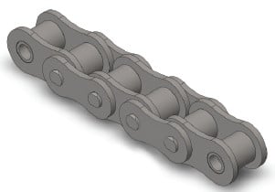
Roller link plates are 1 dimension thicker to increase strength. Side plates and pins have special coatings to stop rust.
C-Type Roller Chains
Similar as above except the side plates are all conventional thickness. The power of the CS Type chains is lower than the PT Type but higher than the SL sort. Attachments with common dimen-sions may be used for this series and so they may be usually utilised on small materials handling conveyors.
P-Ring Chains
Specifi ed on smaller sized pitch roller chains O-Ring chains utilize a rubber seal to keep lubricating grease in even though avoiding the penetration of grime as well as other contaminants into the pin/bush-ing bearing area.
Seal Guard Roller Chains
Specifi ed on larger pitch roller chains Seal Guard chains utilize a stainless steel seal to maintain lubricating grease in when avoiding the penetration of grime and other contaminants to the pin/bushing bearing area.

ep

January 15, 2021

Type 304 Stainless
All parts are produced from AISI Type 304 (18-8) austenitic stainless steel. This material off ers very good chemical and temperature resistance inside a broad range of varied applications. Mainly because Form 304 stainless steel cannot be heat taken care of the mechanical strength and wear overall performance is inferior to normal carbon steel chains.
Sort 316 Stainless
All components are created from AISI Style 316 Molybdenum-bearing stainless steel. The molybdenum gives the alloy far better all round corrosion resistance in contrast with Variety 304 stainless steel particularly greater resistance to pitting and stress corrosion cracking within the presence of chlorides. Mechanical power and dress in efficiency are similar to Type 304 stainless steel chain.
600 Series Stainless
Pins, bushings and rollers are made from 17-4PH stainless steels which can be age hardened for improved resistance to dress in elongation. The corrosion resistance of this series is related (however slightly inferior) to Style 304 stainless steel. The working temperature choice of this material however can be not as wide as Style 304 stainless steel.
Mega Chain:
All components are made from AISI Kind 304 (18-8) austenitic stainless steel. Out there in two versions (Mega Chain and Mega Chain II) which use diff erent physical confi gurations to obtain additional strength which is similar to that of carbon steel chains. The working loads of those chains are superior to that of common 304 stainless steel chains due to a higher pin/bushing bearing parts. In addition the two versions possess a unique labyrinth form seal style and design that assists prevent the penetration of abrasive foreign materials to your internal wearing parts.