Category Archives: shear pin coupling

ep

June 8, 2020

Ever-Power Geared Motors with Worm Gearing – Modual & Customizable drive technology
Worm gear devices from Ever-Power DRIVESYSTEMS especially show their strength in applications where high gear ratios are essential. Our worm geared motors are therefore optimally suited for use in intralogistics, packaging technology and the food & beverage industry.
Four great reasons for Ever-Power worm geared motors:
Rugged
Our worm geared motors have a higher overload capacity
Maintenance Friendly
Washdown versions allow simple and efficient cleaning of the drive system.
Corrosion protection
The NSD tupH sealed surface area conversion is exceptionally chemical, corrosion and abrasion resistant.
Flexibility
Our modular design give users optimum freedom.
The modular system for maximum flexibility: Our Ever-Power worm gear units
There are numerous applications that require drive systems, and each of these has its own unique requirements. The EP series Ever-Power worm gear motors could be quickly and effectively adapted to meet your needs.
Ever-Power worm gear devices impress with their high power density and small style. If required, we can also supply them with the highly effective nsd tupH surface treatment.
In addition to the basic Ever-Power casing, you can expect an extensive type of bolt-on parts to customize the product including torque arms, shaft covers and output flanges. These can be very easily field installed, but we will also be pleased to assemble the individual components for you.
Find out more about our modular SI worm geared motors!
Find out more
Simple and Clean: The Ever-Power worm gear device SMI
SMI worm gear models feature a clean, corrosion-resistant alluminum alloy casing. Optional nsd tupH surface conversion makes the product ideally suited for harsh and challenging industries like food processing and pharmaceuticals.
Versatile input designs such as NEMA, IEC or direct motor mounts in additional foot or flange mounted housing designs.
Ever-Power worm geared motors: Compact and efficient
In 2001, Ever-Power engineers developed a Ever-Power concept, which combines all elements of the apparatus unit in a one-piece housing. At that time, no-one guessed that this design would end up being the global standard for equipment unit housings.
The reason behind the success of our Ever-Power housing is simple: Through the compact arrangement of all gear unit elements, geared motors achieve higher drive torques and an increased axial and radial load capacity. Our worm equipment products proudly feature this housing design concept.
WORM GEAR MOTORS
Ever-Power EP worm gear motors are the option for applications requiring a part turn, optional dual output, or an inability for the engine to be back again driven. The DC correct angle equipment motors are created for continuous and intermittent duty operation. Our right angle gear reducers are designed with several mounting plate options, making them ideal for a number of DC motor based applications. We offer 12 ratios ranging from 5:1 to 100:1.
FEATURES
1/43 to 3/8 HP
12, 24, 90, 130, 180 VDC, 115 FWR
9 – 475 RPM
1.5 – 315.9 in-lb rated torque
Frame Size 60, 80, 108 mm
5:1 – 100:1 standard ratios
Standard brush life of 2000+ hours (varies by application)
Ever-Power Worm Gear Motors are designed to generate high torque in a little package size. Worm Gear Motors are excellent for applications that want a self- locking or breaking feature since the result shaft can’t rotate when there’s no power applied. Additionally, Worm Gearheads can transfer motion in 90 degrees. With various reduction ratios, precision cut gears, voltages and sizes, EP Items has a DC Worm Gear Motor solution for your application.
Features and Benefits
Very High Torque Capabilities
Self-Locking / Braking Features
Motion Transfer of 90 Degrees
Capability to Handle Large Gear Decrease Ratios
High Durability
Low Noise
Flexible Configuration
Applications
Security Door Locks / Industrial Conveying Systems / Security Gates / Oral Chair / Ambulance Cots & Stretchers Quite a few DC Motors could be complimented with one of our Worm Gearheads. ISL Items will work with you to design and manufacture a Worm Gear Engine that may optimize the functionality of your unique application.

Built to your unique requirements
Electric motor Type: Brushed / Brushless / Coreless
Voltage
Output Speed
Power
Current
Torque
Reduction Ratio
Shaft Material & Size
Gear Material
Shaft Configuration: (D Cut / Round / Splined / Other)
General Size Parameters (L, W, H)
Encoder Type: Optical / Hall Effect
Additional Assembly Requirements (lead wires, connectors, etc.)
Tough, compact, eye-catching!

Due to the unique combination of optimized worm wheel materials with particular lubricants, optimized shape, this powerful engine achieves high levels of performance and torque. The casing machined on all sides allows diverse mounting options. Dual chamber shaft seals are used as standard.

The low contour design makes it ideal for implementing applications e.g. in the meals industry. The housing does not have any recesses, which simplifies cleaning – an especially important feature for areas with stringent hygiene requirements.

Technical Data
Number of sizes:6
Power Range:0.12 – 7.5kW
Output torque range:50 – 1,300Nm
Ratio:3 – 3,400
Output option:output shaft, output shaft on both sides, hollow shaft, hollow shaft with shrink disc
Assembly/mounting:uniblock, flange, torque arm, foot
These simple motors involve some great characteristics which make them suitable for an array of applications!
They are usually low speed but with the capacity of extremely high torque. Worm drives provide a brake feature (by the nature of their design) this means when there is absolutely no power applied to the worm drive, the strain cannot turn the electric motor. They offer a right angle (or also left position) gearbox for useful mounting in tight areas.
Really the only downfall these have is low efficiencies. actually the very best worm gear drives only have an efficiency between 60-80%
DC motors fitted with a worm equipment drive can fulfill all your drive
requirements where you will need high torque and reduce speed rotation

Technical Description:
Motor casing:galvanized metal or painted
Magnets:sintered ferrous metal
Armature shaft bearings:sintered bronze metal bushes/ball bearing
Gearbox housing:plastic material or aluminum/zinc die-casting
Worm wheel:steel
Pinion wheels:plastic, metal or bronze
Uses:
General machine construction, automated machines, agricultural
technology, business devices, laboratory appliances, medical home appliances,
traffic & conversation technology, photographic/optical equipment
Reversible High torque Turbo Worm Gear Electric motor JGY370 DC 12V 40RPM
Reversible High torque Turbo Worm Gear Motor JGY370 DC 12V 40RPM

Features:
The engine is Gear DC motor with micro-turbine worm, you can change the wiring-connection to change motor rotation.
Turbo worm geared engine with self-lock, that is, regarding motor without electric, the output axis is fixed, self-lock.
The reducer output shaft arranged vertically with the engine shaft, whole engine output shaft relatively-short than general gear engine, widely used to be installed the dimensions requirements strictly occasion.

Specifications:
Model: JGY370
Voltage: DC12V
No load speed: 40r/min
Output torque: 5.6kg.cm
Rated current: 0.06A
Weight: 163g
Application: open the home window, door, Mini winch. Ect.
Planetary / Spur / Worm Gearbox
Custom housing to meet your dimensional requirements
Custom shaft options: extended, slotted, cross drilled, hollow shaft etc
Custom winding to meet your unique application needs
Lead wire options: particular lengths, high temperature shrink, Teflon leads, pins, connectors, cable harnesses etc
Bearing & lubricant choices for high temperature/humid operations
Encoders, gearboxes, sprockets and pulleys installation
App: Garage door opener, gate operator, parking barrier, wheelchair, electric automobile, shopping cart software, water pump, flooring polisher, truck lift, salt spreader, stair lift, hospital bed
Description
Runs on the metal gear box
Durability and a higher torque output
Output shaft is self-locking
Rated voltage is 12v and can achieve 40RPM
The 6VDC 40RPM, 111.1oz-in Worm Gear Motor runs on the steel gear box for strength and a high torque output. Because of the special mechanical structure of the worm drive the motor output shaft can be self-locking and can’t be rotated. This part runs on the two wire connection and facilitates direction control as well as PWM velocity control. Rated voltage can be 12v and will obtain 40RPM, with a torque of 8kg/cm.

Specifications
Operating Voltage: 6 – 15 V
Rated Voltage: 12V
No-load Speed: 40 RPM
No-load Current: 35 mA
Rated Torque: 32 RPM
Rated Current: 180 mA
Ranked Torque: 2.2 kg.cm
Rated Power: 1.1 W
Stall Torque: 8 kg/cm
Stall Current: 1 A
Reduction Ratio: 1:150
Weight: 167 g
Size Name:20RPM
The entire body of the electric motor output shaft relative to the general direction of gear electric motor short, widely adapted for some of the installation dimensions of the aspect is necessary.This section is ideal for small motor configuration high speed ratio, the installation space is limited occasions, large torque output.
Application:
Label machines, handy remote control curtains, automated voltage regulators, barbecue grills, ovens, washers, waste materials disposal machines, household appliances, coin machines, paper currency recognizers, automated actuators, coffee devices, towel machines, printing machines and Stage lighting.
Specifications:
Color: Silver
Voltage: DC12V
Load torque: 10KG.CM
No-load speed choice: 5rpm / 6rpm / 20rpm / 40rpm / 62rpm(optional)
Purpose:
Banking equipment, security deposit boxes, paper feeder, intelligent gas meter, tissue machines, auto parts, advertising devices, analytical instruments, electronic games.
Note:
The color of the item may vary slightly due to photography and your own computer.
Package Includes:
1 x Turbo Worm Geared DC Motor
DC Worm Gear Electric motor SGM-370 12V 6rpm
The turbo metal gear worm electric motor uses a metal gear box for sturdiness and a higher torque output. Due to the special mechanical structure of the worm drive the engine output shaft is definitely self locking and can not be rotated. This part uses a two wire connection and supports direction control along with PWM quickness control. Rated voltage is 12v and can achieve 16RPM.
Specification:
Operating Voltage: 6 – 15 V
Rated Voltage: 12V
No-load Speed: 6 RPM
Rated Torque: 14 kg-cm
Weight: 156 g

ep

June 6, 2020

Single reduction worm gearing offers high ratio reduction with few shifting parts in a close-coupled compact drive. The proper angle set up of driving-to-driven machine takes a the least space. Input and output shafts can be prolonged in either or both directions in horizontal or vertical arrangements adaptable to any installation requirement. Efficient electric motor speeds are decreased to gradual speed requirements of several industrial machines in a single reduction.
Product Features
Ratios 5:1 to 70:1
Hollow & Solid Output Shafts
Vertical & Horizontal Mounting
Fan Cooled (Standard)
Motor Mounts (C-Encounter Adapters or Scoops)
Cast Iron or Steel Housings
Products
The exclusive usage of the involute Helicoid Thread form (with departing side contact) on the worm and gear provides for high efficiencies, and long service lifestyle. The hardened ground and polished alloy steel worm develops a simple, work hardened surface on the bronze equipment. For this reason worm gears put on in and improve with extented service while various other gears are worm gear speed reducer deteriorating. Ever-Power offers a broad collection of model configurations, sizes, ratios, and components from our standard product line.
Fabricated Designs
If the application involves severe shock loads or possible housing damage from external sources (as in steel mills or mobile gear applications) Ever-Power can provide fabricated steel housings with up to 48″ center distances. Fabricated housings provide optimum rigidity and strength which allows the transmission of higher horsepower levels than are feasible with regular cast iron units. Extra heavy part plates connect the worm and equipment shaft bearing supports, assuring appropriate meshing of the gear under all load conditions. In smaller sized sizes, fabricated metal reducers are interchangeable with Ever-Power regular cast iron reducers.
Custom Designs
Ever-Power can offer custom speed and reversed engineered reducers for the application, be it a fresh project or a primary drop-in replacement for a competitor’s acceleration reducer. Fabricated metal reducers enable Ever-Power to complement a competitor’s footprint, centerline, and shaft height allowing a primary drop-in alternative saving the client time and money.
Long – Quiet Life
All worm gears in Ever-Power reducers are manufactured from phosphorous bronze. Our design also includes a hardened, surface and polished alloy steel worm. This mixture develops a even, work-hardened mating surface of the bronze gear which increases with prolonged service.
Worm gearing is a class of equipment reducers that utilizes correct angle, nonintersecting shafts. This style of reducer provides clean and quiet operation and permits the probability of large quickness reductions. These gears can be found from share in a wide variety of ratios, from only 4:1 to as much as 3600:1. The small design and construction allows worm gear reducers to be positioned in a relatively small space. Thus, high reductions in a limited package size can be achieved with this configuration. Our worm equipment features the constant sliding tooth action between worm and one’s teeth. This increases the tolerance for weighty loads and shock loads. Worm gear drives provide users high reducing convenience of relatively low cost when compared to some other types of gearing.
The use of worm gearing extends across many industries including food, beverage and grain and has many applications. Some applications that use worm gearing are: conveyors, mixers and bucket elevators.
Ever-Power worm equipment reducer gearbox series bottom on years of encounters uses designed teeth surface with unsurpassed torque transfer overall performance with great overall performance, efficency and cost.Worm gear system transmits power through sliding get in touch with, leading to extremely low vibration , noise, small backlash and self-locking property
-Housing:Onetime we casting creats great rigidity for serious impacts. Outer cooling fins and internal lubrication oil diversion channel design to increase heat dissipation.
-Worm Shaft: Manufactured with Carbon alloyed Metal S45C or SCM415, precison machined and carburized to HRC45 or HRC60, after that for precision tooth grinding to make sure maximum contacting.
-Worm Wheel: Manufactured with Carbon alloy ALBC2, teeth are machined by precision CNC hobbing machine to sustain high impact.
A worm gear reducer is one type of reduction gear box which includes a worm pinion input, an output worm gear, and features a right angle output orientation. This type of reduction gear package is normally used to have a rated motor rate and create a low speed result with higher torque value based on the decrease ratio. They often can resolve space-saving problems because the worm equipment reducer is one of the sleekest reduction gearboxes available due to the little diameter of its output gear.
worm gear reducerWorm equipment reducers are also a popular type of acceleration reducer because they provide the greatest speed decrease in the tiniest package. With a high ratio of speed reduction and high torque result multiplier, it’s unsurprising that lots of power transmission systems utilize a worm gear reducer. Some of the most common applications for worm gears are available in tuning instruments, medical assessment equipment, elevators, security gates, and conveyor belts.
SW-1 and SW-5
Torque Transmission offers two sizes of worm equipment reducer, the SW-1 and the SW-5 and both are available in a variety of ratios. The SW-1 ratios include 3.5:1 to 60:1 and the SW-5 ratios include 5:1 to 100:1. Both of these options are manufactured with durable compression-molded glass-fill polyester housings for a durable, long lasting, light weight speed reducer that is also compact, non-corrosive, and nonmetallic.
Features
Our worm equipment reducers offer an option of a solid or hollow result shaft and feature an adjustable mounting position. Both the SW-1 and the SW-5, nevertheless, can withstand shock loading much better than other decrease gearbox designs, making them ideal for demanding applications.
Rugged compression-molded glass-fill up polyester housing
Light weight and compact
Non corrosive
Non metallic
Range of ratios
SW-1, 3.5:1 to 60:1
SW-5, 5:1 to 100:1
Grease Lubrication
Solid or Hollow output shaft
Adjustable mounting position
Worm Gear Reducers also called worm gearbox or worm swiftness reducers. Worm gear reducers are used for speed reduction and increasing the torque for electric powered electric motor drives. You can choose to attach your NEMA motor to the reducer utilizing the NEMA C face flange or use a coupling. If you want a coupling for the output or input shaft observe our coupling section for selecting a coupling. You can expect four assemblies left hands and right hands and double result shaft and shaft insight and shaft result. Interchangeable with many worm gear manufactures. See data sheet in product overview for diamensions. If you don’t see your type, make sure you Contact Us.
8 Ratios Available from 5:1 to 60:1
7 Gear Box Sizes from 1.33 to 3.25″
Universally Interchangeable Style for OEM Replacement
Double Bearings Used on Both Shaft Ends
Anti-Rust Primer Applied Outside and inside Gearbox
Shaft Sleeve Protects All Shafts
S45C Carbon Steel Shafts
Flange Mount Versions for 56C and 145TC Motors
Ever-Power DDVM series triple-reduction worm gear speed reducers can be found in ratios from 5000:1 to 175,000:1 and middle distances from 7” to 20” (larger sizes available on request). Output torque ranges from 33,000 in lbs. for the 7” CD DDVM-70 to 582,900 in pounds for the DDVM-200. Mechanical HP insight requirements are from 0.09 HP for the 175,000:1 7 in CD reducer to 6.25 HP for the 5000:1 20” CD unit. These reducers can be found in four configurations: horizontal, vertical, shafted, and shaft installed.
These reducers are well suited for water/waste-water products drive applications such as thickeners and clarifiers, which require a vertical down shaft. Other obtainable configurations also make Ever-Power triple reduction reducers perfect for make use of on mixers, elevators, solar power panels, astronomical telescopes, indexing tables, hoists, conveyors, or various other process or components handling systems where large torques/slower speeds are needed.
These reducers are also available with a helical principal reduction stage and so are termed the HDVM series
Product Features
Ratios 5000:1 to 175,000:1
HP from 0.09 to 6.25.
Output Torque to 583,000 in lbs.
Output RPM only 0.01 with a 1750 RPM input.
Ideal for ultra-slow quickness, high torque applications
8 Ratios Available from 5:1 to 60:1
7 Gear Box Sizes from 1.33 to 3.25″
Universally Interchangeable Style for OEM Replacement
Double Bearings Applied to Both Shaft Ends
Anti-Rust Primer Applied Outside and inside Gearbox
Shaft Sleeve Protects All Shafts
S45C Carbon Steel Shafts
Flange Mount Versions for 56C and 145TC Motors
Description
The HDR Series worm equipment reducers are used in low to moderate horsepower applications to reduce speeds and increase torque. Worm gear reducers can be found in direct or indirect drive, direct drive models are 56C or 145TC flange attach with either right, still left or dual output shafts or a hollow bore result. The indirect drive models are shaft input-shaft output boxes for make use of with sprocket or pulley drive systems. They offer an effective low priced solution to speed decrease and improved torque, with higher tolerances for shock loading than helical equipment reducers.
In order to select a gearbox speed reducer, you will have to determine the required torque and support factor for the application. Click on “Specs” above for a desk that will aid in determining the service factor. For service factors above 1.0, multiply the mandatory torque by the assistance factor.
Our standard 700 Series – the heart of Ever-Power rate reducer products – has been serving industry reliably for over 40 years. Its proven modular style has set the market standard for performance and may be the most imitated item in the current worm gear quickness reducer market. But why accept a knock-off when you’re able to have the initial – from Ever-Power.
Specifications
11 basic solitary reduction sizes
8 basic dual reduction sizes
1/6 – 25 HP
5:1 – 100:1 ratios single reduction
100:1 – 3600:1 ratios double reduction
Non-flanged, NEMA C-face quill, and coupled input styles
Projecting and hollow result shafts
Projecting diameters from 1/2″ to 2-1/4″
Hollow result bore diameters from 5/8″ to 3-7/16″ (with over 20 bore sizes in share)
Product Features
The 700 Series’ large oil reservoir provides efficient heat dissipation and lubrication for longer operating lifestyle.
Its multi-position mounting flexibility permits installation in virtually any position.
Housings are straddle-milled, top and bottom level, for precise alignment of horizontal and vertical bases.
Internal baffles assure positive, leak-free venting.
The 700 Series’ rugged casing, fabricated of fine-grained, gear-quality cast iron, provides maximum strength for optimum durability, in addition to greater precision during worm and gear alignment.
Ever-Power 700 Series high-strength bronze worm gear is straddle mounted between heavy-duty tapered roller bearings to increase thrust and overhung load capacities, sizes 713-760.
Our 700 Series’ high-strength steel result shaft assures capacity for high torque and overhung loads.
Pipe plugs allow easy fill up, level, and drain in virtually any mounting position.
The 700 Series’ super-finished oil-seal diameters on both input and output shafts extend seal life.
Both 2D and 3D CAD drawings are available in our eCatalog.
TheIncreased Quality! Industrial Rated! Inexpensive!One-piece gearcase, without exterior ribs, is made from close-grained cast iron and for rigid equipment and bearing support. In addition, it offers excellent warmth dissipation.Dual lip, spring-loaded seals guard against oil leakage and stop dirt from entering.Stepped shafts with oversized ball andtapered roller bearings.Carbon steel shafts for greater strength.High tensile strength cast bronze worm wheel and hardened and floor alloy steel worm made intregal with the shaft for long and trouble-free life.Essential oil sight gauge for ease of maintenance (not available upon sizes 25 and 34).Factory oil loaded.Every unit test run just before shipment.Universal mounting with bolt-on ft.Highly modifiable design.All of this at substantially cheaper prices than you have been accustomed to paying for reducers of lesser quality. Less

ep

June 4, 2020

Our standard 700 Series – the heart of Ever-Power speed reducer product line – has been serving industry reliably for over a decade. Its proven modular style has set the market standard for efficiency and may be the most imitated product in the current worm gear velocity reducer marketplace. But why settle for a knock-off when you can have the original – from Ever-Power.
Specifications
11 basic single reduction sizes
8 basic dual reduction sizes
1/6 – 25 HP
5:1 – 100:1 ratios single reduction
100:1 – 3600:1 ratios double reduction
Non-flanged, NEMA C-face quill, and coupled input styles
Projecting and hollow output shafts
Projecting diameters from 1/2″ to 2-1/4″
Hollow output bore diameters from 5/8″ to 3-7/16″ (with over 20 bore sizes in share)
Product Features
The 700 Series’ large oil reservoir provides efficient heat dissipation and lubrication for longer operating existence.
Its multi-position mounting versatility permits installation in practically any position.
Housings are straddle-milled, top and bottom, for precise alignment of horizontal and vertical bases.
Internal baffles assure positive, leak-free venting.
The 700 Series’ rugged casing, fabricated of fine-grained, gear-quality cast iron, provides optimum strength for optimum durability, and also greater precision during worm and gear alignment.
Ever-Power 700 Series high-strength bronze worm equipment is straddle mounted between heavy-duty tapered roller bearings to increase thrust and overhung load capacities, sizes 713-760.
Our 700 Series’ high-strength steel result shaft assures capacity for high torque and overhung loads.
Pipe plugs allow easy fill up, level, and drain in virtually any mounting position.
The 700 Series’ super-finished oil-seal diameters on both input and output shafts extend seal life.
Both 2D and 3D CAD drawings can be found in our eCatalog.
Ever-Power worm gearboxes have earned a status to be an industry benchmark worldwide. Our success came from our relentless drive for quality with state-of-the-art technology, all while offering worm gearboxes are affordable prices. High versatility accorded through a wide choice of mounting choices, shaft configurations and motor interfaces, makes the Ever-Power worm gearbox the default choice for the market. The helical-worm and the double-worm version, with or without the torque limiter, add up to the advantage, creating an extremely versatile drive system.
Ever-Power Worm gearboxes provide high torque with low velocity gear ratio. Being basic and compact in style, these gears can achieve higher gear ratio than the helical gears. These worm decrease gears having screw type qualities are similar to helical gears, but its helix position is typically comparatively bigger) and its body is normally quite long in the axial path. The gears in these gearboxes can be correct or left-handed depending upon the purpose.
Mounting option include universal housing, side flanges, foot (horizontal and vertical), shaft mounted with torque arm. Available in Solid shafts (single or double), with torque arm or torque limiter.
Worm reduction gears features
Principles
A worm gear is a kind of interlocking gear composed of a worm shaft and worm wheel. The worm is usually shaped like a screw and the worm wheel can be a kind of gear machined to have a tooth profile with the same configuration.
The operation of a worm gear is comparable with that of a bolt and nut. The principle is the same as a nut that is fixed so that it cannot rotate and therefore progresses in the axial path when the bolt is certainly turned.
The look of a worm gear is thought of through the relationship between the rack and spur gear on the middle plane of the worm wheel.
Features
High reduction ratio One rotation of the worm rotates the worm wheel simply by one tooth. Because of this, in a 1 speed reduction gears, the wheel could be manufactured so that it will be rotated 1/60 (1/120 in particular applications).
Orthogonal shaft The shafts are aligned orthogonally because of the structure. This feature can help you layout the turning tranny direction at the right angle.
The arbitrariness of the rotation direction The screw direction of the worm can be clockwise or counterclockwise (generally clockwise). It is possible to change the rotation direction of the worm wheel by changing the screw direction.
A wide variety of shaft layouts The wide variety of shaft layouts is among the top features of interlocking gears.For example, right shaft output, remaining shaft output, dual shaft input and dual shaft output, etc., combine for a total of 14 types (Determine 2) and, if attachment orientations are included, it is possible to pick from over 40 layouts.
Low noise, low vibration The interlocking of the worm and worm wheel is definitely characteristic since the contact is certainly linear and the relative slide is fantastic. In comparison to rolling power transmission, sound and vibration are extremely low. For this reason, this technology can be used to drive medical products, elevators and escalators, etc.
The primary specifications of worm reduction gears
MA Series(Small)
Center distance(mm) 32,40
Reduction ratio 10,20,30,40,50,60
Input capacity(kW) 0.1~1(at an input of 1800 rpm)
Output torque(N・m) 20~66
Input speed(rpm) 0~1800
MA Series(Medium)
Center distance(mm) 50,63,80,100,125,140,160
Reduction ratio 10,15,20,25,30,40,50,60
Input capacity(kW) 0.4~30(at an input of 1800 rpm)
Output torque(N・m) 900~3570
Input speed(rpm) 0~1800
S Series
Center distance(mm) 50,60,70,80,100,120,135,155,175,200,225,250,300,350,400,450,500
Reduction ratio 10,15,20,25,30,40,50,60
Input capacity(kW) 0.3~255(at an input of 1800 rpm)
Output torque(N・m) 50~56600
Input speed(rpm) 0~1800
Key points when choosing a worm reduction gears
Selection
When selecting a worm reduction gears, the procedures for selecting the correct gear are described in the maker catalogs and the series and models should be selected according to those procedures. Particular care ought to be taken in important areas such as selecting the strain index, calculating the overhang load and examining the heat rated capability from the manufacturer.
Cautions during use
When utilizing a worm decrease gears, heat produced during the initial period of make use of is high and running-in operation at 1/4, 1/2 and 3/4 of rated torque for eight hour periods is key to sufficiently attaining the performance of the worm reduction gears.
Maintenance and inspection
After completing running-in procedure (approximately 50 hours), it’s important to change the lubricating oil and also to change the lubricating oil after that about 1 time each year according to the procedure manual provided by the manufacturer.
Product Description
The Worm Reduction Gear Box is supplied by our company is of supreme quality. Our products are made by using premium quality material and progress technology at our vendors end. They are widely used in a variety of sectors. Our items are easily available at an extremely low market prices.
Motor Mount Frame Options
TEC Motors, worm decrease gearbox.
Option A-160 B5 Body, Flange Mount.
Option B-132 B14 Frame, Face Mount.
Option C-100/112 B5 Frame, Flange Attach.
High efficiency and secure operation. High load capability and overload functions. Result Torque = (Power (kW) x 9550 (Constant))/ Gearbox output speed (rpm).
Higher ratios on request dependent on service factor (40:1, 50:1, 60:1, 80:1, 100:1)
DESCRIPTION
Wormgears of the VF series are milestones for the market worldwide. They succeeded in combining uncompromising quality with stateoftheart technology amd renown price effectiveness.Absolute versatility is distributed by the wide choice of several installation options, shaft configurations and electric motor interface, all offered as standard. The helicalworm and the doubleworm version, with or without the torque limiter, also accumulate, creating a highly versatile drive system.
ADDITIONAL INFORMATION
AMP
0.42 A
EFFICIENCY
84%
HP
0.12
KW
0.09
RATIO
7
RPM
200
TEMPERATURE RATING
20 level C TO 80 level C
TORQUE
4 Nm
HSN
8483.40.00
WARRANTY PERIOD
12 Months
The worm reduction gears come in two series: X and H.
The series X, featuring a worm and worm wheel set, is available in versions XA with shaft and XF-XC with mounting provisions for motor.
Version XF (bell housing + coupling) offers great versatility to match a broad range of applications and higher efficiency than the compact series XC, where the emphasis is on space performance.
Series H offers the same features since series X with an added plus: a spur gear pre-stage at the input end provides higher overall performance and a broader range of ratios compared to the X series.
Body sizes 110 and 90 feature a cast-iron housing cast enbloc, whereas smaller sizes use die-cast aluminium housings. The worm shaft is manufactured from casehardened and hardened alloy metal and ground-finished.
The worm wheel includes a cast iron hub with cast bronze insert. Hollow output shaft is supplied as standard.
Broad range of options available:
second input, output flange, single or dual extension result shaft, torque limiter with through cable, torque arm.

ep

June 3, 2020

Our worm gear worm reduction gearbox reducers offer a choice of a good or hollow result shaft and show an adjustable mounting placement. Both SW-1 and the SW-5, however, can withstand shock loading much better than other reduction gearbox designs, making them well suited for demanding applications.
Rugged compression-molded glass-fill polyester housing
Light-weight and compact
Non corrosive
Non metallic
Range of ratios
SW-1, 3.5:1 to 60:1
SW-5, 5:1 to 100:1
Grease Lubrication
Solid or Hollow output shaft
Adjustable mounting position
Worm Gear Velocity Reducers is rated 5.0 out of 5 by 1.
8 Ratios Available from 5:1 to 60:1
7 Gear Box Sizes from 1.33 to 3.25″
Universally Interchangeable Style for OEM Replacement
Double Bearings Used on Both Shaft Ends
Anti-Rust Primer Applied Outside and inside Gearbox
Shaft Sleeve Protects All Shafts
S45C Carbon Metal Shafts
Flange Mount Versions for 56C and 145TC Motors
Our standard 700 Series – the heart of EP Gear’s swiftness reducer product line – has been serving industry reliably for over 40 years. Its tested modular design has set the industry standard for performance and is the most imitated item in the current worm gear speed reducer market. But why settle for a knock-off when you’re able to have the initial – from EP Gear.
Specifications
11 basic single reduction sizes
8 basic double reduction sizes
1/6 – 25 HP
5:1 – 100:1 ratios single reduction
100:1 – 3600:1 ratios double reduction
Non-flanged, NEMA C-face quill, and coupled input styles
Projecting and hollow result shafts
Projecting diameters from 1/2″ to 2-1/4″
Hollow result bore diameters from 5/8″ to 3-7/16″ (with over 20 bore sizes in stock)
Product Features
The 700 Series’ huge oil reservoir provides efficient heat dissipation and lubrication for longer operating life.
Its multi-position mounting versatility permits installation in practically any position.
Housings are straddle-milled, best and bottom level, for precise alignment of horizontal and vertical bases.
Internal baffles assure positive, leak-free venting.
The 700 Series’ rugged casing, fabricated of fine-grained, gear-quality cast iron, provides optimum strength for optimum durability, as well as greater precision during worm and gear alignment.
EP Gear’s 700 Series high-strength bronze worm equipment is straddle mounted between heavy-duty tapered roller bearings to improve thrust and overhung load capacities, sizes 713-760.
Our 700 Series’ high-strength steel output shaft assures convenience of high torque and overhung loads.
Pipe plugs allow easy fill up, level, and drain in virtually any mounting position.
The 700 Series’ super-finished oil-seal diameters on both input and output shafts extend seal life.
Both 2D and 3D CAD drawings can be found in our eCatalog.
GEARBOX REDUCERS
Right angle gearboxes (worm and planetary) are rugged and built for 90° turns. Inline reducers (parallel shaft and planetary) are a perfect match for motors with high insight speeds, or when gearmotor efficiency is important. Get in touch with our technical sales personnel for help determining which gearbox answer is most beneficial for you.
RIGHT ANGLE REDUCERS
WORM GEAR REDUCER
EP’s worm equipment reducers were created with a hollow bore and invite for a corner turn with optional dual output. The reducers can be found in 12 ratios ranging from 5:1 to 100:1, with non-back-drivable ratios 30:1 and higher. Our correct angle gearboxes are designed with five mounting choices providing versatility when incorporating the reducer into product.
RIGHT ANGLE BEVEL GEARBOX
bevel-right-angle-gearbox
The proper angle bevel gearbox combines the top features of our correct angle worm and planetary inline reducers. With a solid and efficient right angle configuration, our right angle planetary gearboxes offer a robust solution. The right angle bevel gearbox comes in 18 ratios ranging from 5:1 to 1000:1, in fact it is back-drivable at all ratios.
INLINE REDUCERS
I-SERIES PLANETARY GEARBOX
i-series-planetary-gearbox
Our I-Series little planetary gearbox configurations supply the smallest footprint and quietest operation of our rate reducers. These gearboxes are made to handle varying loads with small backlash. With frame sizes 52cm, 62cm, and 81cm, 12 ratios which range from 5:1 to 308:1, we have a solution to fit your needs. Our 52 frame size can be available with plastic-type material gears for noise-delicate applications.
INLINE PLANETARY GEARBOX
inline-planetary-gearbox
Our inline planetary gearbox configurations provide the highest efficiency and best output torque of all our velocity reducers. These gearboxes are created to deal with varying loads with small backlash. Planetary equipment reducers operate more quietly than parallel shaft reducers. With 18 ratio options which range from 5:1 to 1000:1, we have a solution to fit your needs.
PARALLEL SHAFT GEARBOX
parallel-shaft-gearbox
Parallel shaft gearboxes are the top choice for constant duty applications. Their gear cluster design provides a highly effective method for dissipating warmth. Parallel shaft gearboxes have the shortest length of our inline gear reducer options so they work well in environments with limited space. Our parallel shaft equipment reducers provide an affordable drop-in replacement solution for most little parallel shaft gearmotors.
Wormwheel gearboxes pass several names, including 90-degree gearboxes, right angle gearboxes, acceleration reducers, worm equipment reducers and worm drive gearboxes. Gear reduction boxes include a gear arrangement in which a equipment in the kind of a screw, also called a worm, meshes with a worm gear. These gears are typically made from bronze and the worms are steel or stainless steel.

While worm gears are similar to a spur equipment, the worm gearboxes are significantly smaller than other equipment reduction boxes. A principal benefit of worm equipment reducers is certainly that they produce an output that is 90° from the insight and can be utilized to transmit higher torque or decrease rotational speed. Most often, a worm gearbox has right hand threads; to improve the path of the output, a left-hands thread worm gearbox is necessary.
Worldwide HdRS133-10/1-R Cast Iron Right Angle Worm Equipment Reducer 10:1 Ratio

Cast Iron Worm Equipment Reducers are available in center distances 1.33 – 3.25 inches in ratio’s from 5:1 to 60:1. The devices possess a one piece #Fc20 all cast iron housing, NEMA engine quill style insight flanges or shaft inputs, come pre-packed with synthetic oil and have a 1 year warranty.

Features:
Tapered roller bearings upon the input and output shafts
Embedded double-lip oil seals
Anti-rust primer applied inside and outside of the gearbox
Air dry special black paint
Product Specifications

OUTPUT SPEED (RPM) 175
OVERHUNG LOAD LBS. 300
EFFICIENCY 86
BRAND EP
MANUFACTURERS PART Quantity HdRS133-10/1-R
CROSS REFERENCE Boston 713; Grove B213
DESCRIPTION Cast Iron Right Ange Worm Gear Reducer
BACKLASH (FT.) (ANGULAR Mins) 27
OUTPUT SHAFT THRUST LOAD (Pounds.) 300
MAX INPUT HP 0.77
MAX TORQUE (IN-LBS.) 247
WCD CENTER INCHES 1.33
GEAR RATIO 10:1

Ever-Power EP series triple-reduction worm gear speed reducers can be found in ratios from 5000:1 to 175,000:1 and middle distances from 7” to 20” (larger sizes available on request). Output torque ranges from 33,000 in pounds. for the 7” CD EP-70 to 582,900 in lbs for the EP-200. Mechanical HP input requirements are from 0.09 HP for the 175,000:1 7 in CD reducer to 6.25 HP for the 5000:1 20” CD unit. These reducers can be found in four configurations: horizontal, vertical, shafted, and shaft installed.

These reducers are ideal for water/waste-water tools drive applications such as thickeners and clarifiers, which require a vertical straight down shaft. Other offered configurations also make Ever-Power triple decrease reducers perfect for use on mixers, elevators, solar panels, astronomical telescopes, indexing tables, hoists, conveyors, or additional process or materials handling systems where large torques/gradual speeds are needed.

These reducers are also available with a helical main reduction stage and are termed the HDVM series

Enclosed Gears / Gearboxes
Enclosed gears, also referred to as gearboxes or swiftness reducers, are open gears contained in a housing. The casing supports bearings and shafts, retains in lubricants, and protects the elements from surrounding conditions. Gearboxes are available in a wide variety of load capacities and speed ratios.

The objective of a gearbox is to improve or reduce speed. Consequently, torque output will be the inverse of the function. If the enclosed drive is certainly a quickness reducer, the torque result increase; if the drive increases speed, the torque output will decrease. Gear drive selection elements include: shaft orientation, swiftness ratio, design type, character of load, gear ranking, environment, mounting position, working temperature range, and lubrication.

Basic Types of Gearboxes

Worm Gear Speed Reducers
A single reduction velocity reducer can achieve up to a 100:1 decrease ratio in a small package. Known as right angle drives, these contain a cylindrical worm with screw threads and a worm. With an individual begin worm, the worm equipment advances only one tooth for every 360-degree change of the worm. So, whatever the worm’s size, the apparatus ratio may be the ‘size of the worm gear to 1′. Higher decrease ratios could be created through the use of double and triple decrease ratios.

Helical Gear Speed Reducers
Provide high-efficiency speed decrease through 1, 2, 3, or 4 pieces of gears. Power is usually transmitted from a high-rate pinion to a slower-speed equipment. Helical gears usually operate with their shafts parallel to each other. Both most common types are the concentric (insight and output shafts are in range) and parallel shaft (input and result shafts are offset). Single-stage helical equipment reducers are usually used for gear ratios up to about 8:1. Where decrease speeds and higher ratios are required, dual, triple, and quadruple gear reduction stages can be used.

Cycloidal Disc Speed Reducers
Different from conventional gearing because they operate without a high acceleration pinion or equipment teeth, and the components operate in compression rather than shear. This is due to the style of the cycloidal discs that roll within a band gear housing, similar to a planetary design. The primary components will be the eccentric cam, the internally flanged output shaft, the discs, and the ring gear casing.

Three Mounting Options
(L-R) Base Mounted, Shaft-Mounted, Gearmotor
(L-R) Base-Mounted, Shaft-Mounted, Gearmotor

Base-mounted reducers, that have feet for bolting, will be the most common.

Shaft-mounted reducers possess a hollow output shaft that slips more than the driven shaft.

A gearmotor combines a specific gearset with a engine. A motorized reducer resembles a gearmotor except that it’s driven by another NEMA C-face motor.

Seals and Breathers
Seals are used between the gear housing and insight and result shafts to retain oil and prevent dirt. The mostly utilized type, the radial lip seal, consists of a steel casing that fits into the housing bore and an elastomeric sealing lip that presses on the shaft. Labyrinth seals are make use of for high-swiftness applications, and consist of a housing with some bands that limit leakage. A breather is a plug with a hole that’s mounted in the apparatus housing allowing airflow and relieve inner pressure.

Lubrication
Enclosed gears are generally lubricated with oil. The most common types of essential oil are rust and oxidation inhibiting, extreme pressure, compounded, and synthetic. Other styles include grease and solid film. Grease can be utilized for worm, planetary, cycloidal, and hypoidal reducers. Common distribution strategies are a splash system and a circulating system
Worm Reduction Gearbox App:

Worm drives certainly are a compact method of substantially decreasing speed and increasing torque. Small electric motors are generally high-speed and low-torque; the addition of a worm drive increases the range of applications that it might be suitable for, particularly when the worm drive’s compactness is known as.

Worm drives are found in presses, in rolling mills, in conveying engineering, in mining sector machines, and on rudders. In addition, milling heads and rotary tables sit using high-precision duplex worm drives with adjustable backlash.

ep

June 2, 2020

This gearbox utilizes a 30:1 ratio worm-drive reduction for applications that require extremely slow and smooth rotational motion. The worm-drive design not merely minimizes backlash but also eliminates back-generating the gearmotor so a position can be kept even when power isn’t applied. The precision ground 3/8” stainless steel output shaft is backed by dual 3/8” ABEC 5 ball bearings to aid lots from any orientation. The ¼” ABS plastic and aluminium structure provides a rigid framework without adding unnecessary weight and is worm wheel gearbox usually easily installed to any flat surface by utilizing the base mounting tabs. Our Standard Spur Gear motors will continue to work with this gearbox (electric motor sold separately). The Vertical Shaft Worm-Drive Gearbox is ideal for turn-tables, time-lapse systems and low-quickness applications that want high precision and torque.

Motor RPM required = 1 / (minutes per rotation desired / 30)
Example: 1 / (10 minutes per rotation / 30) = 3 RPM motor needed to achieve 10 minutes per rotation (at max speed)
Dimensions 3.43″ x 1.93″
Product Weight 5.9oz (0.375 lbs)
Output Shaft Diameter 3/8″ (0.375″)
Motor Size Compatibility Standard Spur Gear Motors

Ever-Power gives you the widest selection of standard, non regular and customised worm gearbox and worm gear motor.

Ever-Power maintains the highest degree of standard in manufacturing of worm gears in gearboxes. From the design of gearbox, materials selection to manufacturing practice of worm gear box and gear electric motor.

Models: 30, 40, 50, 60, 75, 85, 100, 125, 150, 175, 200, 250, 300, 350, 430
Ratio : 5/1 to 4900/1
Middle Distances : 40 mm to 400 mm
Single stage / Double stage
Small Worm Gearbox Versions like C.D. 50, 60, 75, 85, 100 mm and Ratio 30/1 or 40/1 are usually available in stock or can be made on short notice by customer.
Worm gearboxes are having cast iron equipment case, worm shaft is of Alloy Metal, duly hardened and tempered. The worm wheel is constructed of Chill Cast Phosphorous Bronze.

Ever-Power worm equipment boxes have liberal ribbing for increasing high temperature dissipation area, streamlined sump for carrying more oil and fan of ample size which is effective in both part of rotation.

Design Standards:
Wherever applicable, British as well as Indian Design standards are used. Worm Shafts comply with case- hardening Alloy Steels, Worm Wheels conform to phosphorous-bronze as per BS 1400, While Gear case conforms to C.I. Grade 20, IS210.

High reduction gear
Worm and wheel gear pairings provide large speed reduction ratios with only 1 gear pairing in a more compact space in comparison to other styles of gears. We offer up to maximum ratio of 100:1 with this products. Another advantage of the Worm and Wheel equipment pairings is the low level sound they produce. Some drawbacks are the general low efficiency and the fact that they generate heat.

Advantage of EP’s Worm Gears – “Chilly rolled Worm Gears”
1) The hardness of the helicoid surface area has been achieved by function hardening when the frosty rolling was performed, providing Worm gears with better mechanical properties than machined worms because of reality that the metallic fibrous structure has not been cut.

2) The top hardness after cool rolling is increased by 1.2 to at least one 1.3 times when compared with the hardness of the original materials, and the hardness of the helicoid surface area increases to around HB240 to 260.

3) Cold rolled worms are ideal for miniature equipment applications since this could be rotated smoothly without damaging the worm wheels crafted from POM or other soft materials.

4) Due to the implementation of this cold rolling method, the helicoid surface area of EP-Worm (M0.5 to 2.0) comes out with a mirror like finish. Thus, EP-Precision Cold Rolled Worms give a smooth operation and long term durability.

Worm gears are constructed of a worm and a gear (sometimes known as a worm wheel), with non-parallel, nonintersecting shafts oriented 90 degrees to each other. The worm is certainly analogous to a screw with a V-type thread, and the apparatus is usually analogous to a spur gear. The worm is normally the driving component, with the worm’s thread advancing the teeth of the gear.

Just like a ball screw, the worm in a worm gear might have a single start or multiple starts – and therefore there are multiple threads, or helicies, on the worm. For a single-start worm, each full turn (360 degrees) of the worm increases the equipment by one tooth. Therefore a gear with 24 teeth will provide a gear reduction of 24:1. For a multi-start worm, the gear reduction equals the number of teeth on the apparatus, divided by the number of starts on the worm. (This is different from almost every other types of gears, where in fact the gear reduction is a function of the diameters of both components.)
The meshing of the worm and the apparatus is an assortment of sliding and rolling actions, but sliding contact dominates at high reduction ratios. This sliding actions causes friction and high temperature, which limits the efficiency of worm gears to 30 to 50 percent. To be able to minimize friction (and therefore, high temperature), the worm and equipment are made from dissimilar metals – for example, the worm could be made of hardened metal and the gear manufactured from bronze or aluminum.

Although the sliding contact decreases efficiency, it provides very quiet operation. (The use of dissimilar metals for the worm and equipment also plays a part in quiet procedure.) This makes worm gears ideal for use where sound should be minimized, such as for example in elevators. In addition, the use of a softer materials for the gear means that it can absorb shock loads, like those experienced in large equipment or crushing devices.

The primary advantage of worm gears is their capability to provide high reduction ratios and correspondingly high torque multiplication. They can also be used as velocity reducers in low- to medium-quickness applications. And, because their decrease ratio is founded on the number of gear teeth only, they are smaller sized than other styles of gears. Like fine-pitch business lead screws, worm gears are usually self-locking, making them ideal for hoisting and lifting applications.

Worms & Worm Gears
EP Gear’s worms and worm gears provide an effective answer for power transmitting applications requiring high-ratio speed reduction in a limited space using correct angle (90°), non-intersecting shafts. When properly used, worms and worm gears provide the smoothest, quietest type of gearing.

Because the efficiency of a worm equipment drive depends upon the business lead angle and number of begins on the worm – and because increased efficiency is always an objective, the ratio should be kept as low as possible. To run properly, worms and worm gears used together will need to have the same diametral pitch and threads.

Our complete type of worms and worm gears can be ordered through the EP Gear Guaranteed Same Day Shipment Plan for the quickest delivery possible.
Product Features
90°, non-intersecting shaft applications answer highly specialized power transmitting needs.
Our worm gears provide smoothest, quietest type of gearing.
They offer high-ratio speed reduction in minimal spaces.
Their efficiency is easily increased by reducing ratios.
With some ratios, there is level of resistance to back driving.
Offered from 48 DP to 3 DP
Stocked as single, dual and quad start configurations

How exactly to Select High Efficient Worm Gearbox?
The worm gear production process can be relatively simple. Nevertheless, there is a low transmission performance problem if you don’t know the how to choose the worm gearbox. 3 basic indicate choose high worm equipment efficiency that you should know:

1) Helix position. The worm gear drive efficiency mostly depend on the helix position of the worm. Generally, multiple thread worms and gears is more efficient than one thread worms. Proper thread worms can increase performance.

2) Lubrication. To choose a brand lubricating oil can be an essential factor to boost worm gearbox effectiveness. As the correct lubrication can reduce worm gear action friction and temperature.

3) Material selection and Gear Manufacturing Technology. For worm shaft, the material should be hardened metal. The worm gear materials should be aluminium bronze. By reducing the worm equipment hardness, the friction on the worm the teeth is decreased. In worm manufacturing, to use the specialized machine for gear trimming and tooth grinding of worms also can increase worm gearbox effectiveness.

From a big transmission gearbox power to a straight small worm gearbox load, you can choose one from an array of worm reducer that precisely matches your application requirements.

Worm Gear Package Assembly:
1) You can complete the set up in six different ways.

2) The installation should be solid and reliable.

3) Make sure to examine the connection between the motor and the worm equipment reducer.

4) You must make use of flexible cables and wiring for a manual set up.

With the help of the most advanced science and drive technology, we have developed several unique “square box” designed from high-quality aluminium die casting with a beautiful appearance. The modular worm gearbox style series: worm drive gearbox, parallel shaft gearbox, bevel helical gearbox, spiral bevel gearbox, coaxial gearbox, correct angle gearbox. An NMRV series gearbox is certainly a typical worm gearbox with a bronze worm gear and a worm. Our Helical gearbox products comprises of four universal series (R/S/K/F) and a step-less speed variation UDL series. Their structure and function are similar to an NMRV worm gearbox.

In the EP worm gears, the output shaft is offset by 90° from the drive shaft. A dual shaft for double-sided output or a cover for the brief shaft end are optionally available as accessories. EP gearboxes come with a high-quality, long-term synthetic lubricant on the basis of polyethylene glycol, and are therefore maintenancefree. They are characterized by high effectiveness and self-locking.

Please note:
Due to their relatively high backlash (~1-2°), worm gears are not ideal for positioning applications.

Worm Gear applications
Program of worm gears, which is similar to a typical spur and the worm, which really is a cylindrical gear that resembles a screw, permits smaller gearboxes or planetary drives, while retaining torque or power. It’s quite common for worm gears to have got reductions of 20:1, and actually up to 300:1 or greater.

Common gearing includes the unique capability which other gearing components do not have – the “worm” can effortlessly spin the part, but the “gears” cannot maneuver and fully rotate the worm-zone.

What’s the reason behind this inability to rotate the gear-worm?

The angle isn’t deep enough on the worm, so when the apparatus attempts to rotate the worm, high frictional pressure between worm shaft and gear parts keep carefully the zone stuck constantly in place.

Committed to excellence, our employees have the most crucial priority satisfying your equipment building needs and item improvement.

Also, we take pride in our equipment; few producers have the gear to engineer metal parts as exact as we do. Also fewer manufacturing businesses have the machining devices to check the tolerances we can hold.

Being a gearing manufacturer to Automotive level companies, with a diverse way to obtain material types, allow us to achieve the most challenging project requirements. The mixture of robust materials, advanced manufacturer technologies, reliability and our dedication to customer satisfaction makes us a high supplier in advanced gearing and shafting items.

Our gear manufacturing locations have over two decades of worm gear style expertise, gained through many projects that included varied sizes of custom made worm gears to print requirements.

ep

June 1, 2020

Request Custom or
Modified Product
gearbox-PR5
Using Compact Worm Gearbox miniature gears, Ever-Power provides designed and built exclusive, high precision mini gearboxes that cannot be found anywhere else. Our miniature gearboxes are available in several configurations, which includes worm and wheel, cross axis helical, bevel, inline spur, and more. We are able to also provide custom micro gearboxes that are designed and built to meet your specific specifications.
Contact us for the mini gearbox your application requires, or ask for a quote upon a custom micro gearbox.
Miniature Bevel Gearboxes | Micro Bevel Gear Drives | Mini Bevel Gearboxes
Bevel Box
Miniature Cross Axis Helical Gearboxes | Cross Axis Helical Mini Gear
Cross Axis Helical
Miniature Shaft-to-Bore Worm Gearboxes & Speed Reducers
Shaft-to-Bore
Miniature 4 Shaft Worm Gearboxes | Mini 4 Shaft Worm Gear Motors
4 Shaft Worm
Miniature Flange Worm Gearboxes | Micro Flange Worm Gear Drives
Flange Worm
Miniature Inline Spur Gearboxes | Micro Inline Spur Swiftness Reducers
Inline Spur
Compact Worm
Compact Worm
Micro Gearbox Options
Gearboxes are also known as reducers, gear reducers, swiftness reducers, equipment drives, and gearmotors. All terms can be used pretty much interchangeably. Please note that the links for our small gear drives include information on the full selection of frame sizes for that series or style.
Bevel Box Micro Gear Drive
Our bevel package miniature gear drives are app rated for the ideal balance of functionality and cost. Torque could be balanced to meet up your RPM and working life requirements. Lightweight with low backlash overall performance (less than 1°, with choice of 1/2”).
Result torque: up to 7 oz.-inches
Low backlash: ≈1°, option of 1/2”
Rated for input speeds up to 2,000 RPM
Temperature range: -5° to 175°F (-20° to 79°C); optional to -40°F (-40°C)
Cross Axis Helical Miniature Gearbox
Ever-Power’ miniature cross axis helical gearboxes provide relatively high amounts of thrust in a concise package. They offer an output shaft at 90° from the input, and so are obtainable in gear ratios from 1:1 to 40:1. Lightweight but durable, with machined light weight aluminum housings and hardened alloy steel gears.
High efficiency: up to 88% at 1,000 RPM
Low backlash: only ≤30 arc minutes
Rated for input boosts to 4,000 RPM
“Left hand” models available
Miniature 2 Shaft Worm Gearbox
Our miniature 2 shaft worm gearmotors are engineered for ≤30 arc mins of backlash or better. Also known as “shaft to bore gearboxes,” these devices provide a single input shaft that protrudes from reverse sides of the casing; output is usually a keyed bore. Standard single- and double-end shafts can be found and given keys and retainer bands. An array of gear ratios and insight sizes are available to meet your needs.
High efficiency: up to 86% at 1,000 RPM
Low backlash: ≤30 arc minutes or better
Obtainable in ratios from 5:1 to 120:1
Rated for input speeds up to 3,000 RPM
Miniature 4 Shaft Worm Gearbox
Every miniature 4-shaft worm gearbox from Ever-Power features precision-machined hardened steel gears, solid aluminium housings, and long lasting lubrication. They provide two insight shafts on opposing sides of the body, with two output shafts perpendicular to the insight shafts. Our mini 4 shaft worm gear drives deliver high efficiency efficiency with low backlash.
High efficiency: up to 82% at 1,000 RPM
Low backlash: less than ≈2°
Available with gear ratios from 1:1 to 32:1
Rated for input boosts to 4,000 RPM
Miniature Flange Worm Equipment Drive
These micro flange worm gearboxes create an output at 90° from the input. They deliver superior overall performance in an amazing array applications and are built with little footprints, making them perfect for functions where space is bound. They offer high performance with low backlash.
Gear ratios from 6.66:1 to 80:1
High efficiency: up to 83% at 1,000 RPM
Low backlash: only ≤4°
Max. input speed: 3,000 PRM
DC motor option available
Miniature Inline Spur Gearbox
Specifically engineered for encoder applications, Ever-Power micro inline spur gear drives can be found in two frame sizes, and so are rated for speeds up to 3,000 RPM. Aluminium housings and stainless gears and shafts make these inline spur gearboxes challenging and corrosion resistant, for your many demanding applications.
Output torque: up to 125 oz.-inches
Low backlash: less than 15 arc minutes
Available with gear ratios from 4.96:1 to 3600:1
Optional synchro cleats available
Compact Wormwheel Gearbox
These miniature right angle worm gear reducers deliver excellent performance with high efficiency, and show rugged construction for challenging power transfer operations. Available in three gear ratios (5:1, 10:1, 20:1), our small worm gearboxes are designed in extremely small footprints for applications where space is bound.
90° output angle
Gear ratios: 5:1, 10:1, and 20:1
Up to 12.5 inch-lbs. of output torque
Max. input speed: 3,000 RPM
Small footprint: 1.5” x 1.5” x 1.08”
Custom Miniature Gearbox
Ever-Power can engineer and produce a customized miniature gearbox to meet your unique specs. We can produce customized micro gearboxes in virtually any configuration the application requires, with result torque amounts as high as 900Nm. We can work from your own gearbox designs, reverse engineer an existing unit, or assist you to develop an all-new style that provides the performance you will need. Ask for a quote on a custom made miniature gearbox or contact us to discuss your specific requirements.
The Ever-Power Advantage: Little is No Big Problem
Broadest selection of small gear reducers
Greased for life
Ruggedly built
Modifications and unique ratios available
Custom small gearboxes designed to suit
Input & Output Shafts
Input and output shafts with drive important and retainer rings could be supplied to your specifications for just about any of our hollow bore miniature gearboxes. We offer a basic selection of one ended or dual ended shafts to put together in these gearboxes. All gearbox shafts are given keys and retainer bands.
For P and PF series worm and wheel gearboxes make use of our P/PF gearbox shafts.
For Electronic series crossed axis helical gearboxes use our E gearbox shafts.
For F series spur gearboxes, contact our app engineers to discuss your particular needs.
We offer a broad selection of misalignment shaft couplings in in . and metric bore sizes. ” and metric precision surface shafts are available from stock.
Die-cast zinc housing – Various models for hand operation
Compact Worm Gearboxes
4731 to 4742, 4746 to 4767
Perfect for use with crank handle
Main physical dimensions:
P/N 4731 to 4742 40mm x 40mm x 70mm
P/N 4747 to 4767 17mm x 35mm x 42mm
Wide variety of ratios from 1:1 to 30:1
1:1, 2:1 and 2.8:1 are not self locking, all other ratios are.
Max. output torques: 2 Nm to 17 Nm
Hand operation only
Immediate coupling between servo motor and worm gear is one of the crucial strengths of EP worm gearmotors, which combine DC engine technology with exceptional durability and wear resistance. Electric motor and gearbox were created as you single, compact unit. Thanks to their reduced current pull, these gearmotors deliver more accurate control of working temperature and higher performance.
45 W to 250 W rated output power
Gearbox centre-centre size 31 mm and 33 mm
Aluminium gearbox casing
Case-hardened, tempered and ground worm
High tin bronze worm gear
Steel shaft planetary gearboxes
Case-hardened and tempered steel gears
Low noise Range of coupling flanges
We deliver worm gearboxes, spur gearboxes and planetary gearboxes with or without integrated linear business lead screw / ball screw adapted to your flexible modular concept.
Based upon this we are able to select a wide variety of regular customizations to meet the requirements of varied properties that are important for each application.
If your application requires a gearbox with some special property such as for example small dimensions or low weight in relation to power, high efficiency, quiet and vibration-free operation, long life, high level of resistance to vibration, pressure or temperature, integrated linear screw, or a combination of such properties, our product range with more than 1000 different standard gearboxes is most likely a good begin to be able to deliver a product that stands out on your side.
Small gearboxes are high-quality gearboxes for regular drives. The electric electric motor is included with the gearbox right into a single unit (the first gear is on the electric motor shaft). Separate gearboxes for connection to conventional IEC motors may also be supplied on request.
Due to the complexity of the gearboxes’ configuration, they can not be purchased inside our e-shop. Our professionals will be pleased to help you create your selection. We will be happy to send out you documentation or style the right set directly, on demand.
VANE MOTORS WITH GEARBOXES
Combinations feasible with all our vane motors
Coaxial gearbox
Planetary gearbox
Worm gearbox
ATEX combinations possible
Stainless steel options possible
Special wishes possible
Ever-Power worm gearboxes possess earned a reputation to be an industry benchmark worldwide. Our achievement originated from our relentless drive for quality with state-of-the-art technology, all while offering worm gearboxes are affordable prices. High flexibility accorded through a wide choice of mounting options, shaft configurations and motor interfaces, makes the Ever-Power worm gearbox the default choice for the sector. The helical-worm and the double-worm version, with or without the torque limiter, soon add up to the advantage, creating an extremely versatile drive system.
Ever-Power Worm gearboxes provide high torque with low quickness gear ratio. Being simple and compact in design, these gears can achieve higher gear ratio than the helical gears. These worm decrease gears having screw type characteristics act like helical gears, but its helix angle is typically comparatively larger) and its body is generally quite long in the axial direction. The gears in these gearboxes can be correct or left-handed depending upon the purpose.
Mounting option include universal housing, side flanges, foot (horizontal and vertical), shaft mounted with torque arm. Obtainable in Solid shafts (solitary or dual), with torque arm or torque limiter.
EXCELLENT Geared Motors. Ever-Power gearboxes and geared motors are the electro-mechanical key components for low backlash, smoothly running and highly dynamic drive systems.
Our high-performance gear units are designed to withstand the toughest industrial applications.
The gear housings are machined on all sides and permit diverse installation positions and applications, making them much popular in the industry. Consequently our geared motors tend to be to be found within our customers own devices.
The smooth running of Ever-Power gear units and the outstanding load capacity of WATT teeth are achieved with 3D design backed by FEM (Finite Element Method). This tooth geometry guarantees optimum rolling get in touch with under load.
The special tooth root style in mixture with tooth helix angle, tooth depth, the materials used and surface finish maximizes load capacity. This high gearing capacity enables smaller tires to be utilized for the same torque, and smaller gears with extraordinary power density can also increase reliability. Ever-Power geared motors are consequently incredible space savers.
Gearing produced with such micro-geometric precision allows the gearing perform necessary for troublefree rolling get in touch with to be substantially decreased and therefore the gear backlash to be minimized.
Double chamber shaft seals produced by Ever-Power are used as standard in parallel shaft, shaft installed and helical worm gears for a higher level of tightness.
Ever-Power’s modular equipment technology meets the requirements of advanced drive systems:
Excellent power density
Minimum backlash
Smooth running
Diverse mounting options
Maximum reliability
High variability
Precision Worm Gearboxes & Geared Motors
EP’s precision worm gearboxes are made for those more demanding applications where compact size, high torque, high ratio, low backlash, low noise and long lifetime are required. Provided in 9 sizes, these worm gearboxes can be supplied with free input shaft, with hollow bore insight shaft and engine flange, and double decrease mixture units for slow swiftness applications. Using cast iron housings, high quality bronze alloy worm tires and long life bearings, reliability and performance are the key top features of this range.
High Precision Right Position Transmission
Long Lifetime
Wide Selection Of Ratios
Special Surface Treatments

ep

March 27, 2020

Hydraulic motors are found in any program requiring rotational force, also called torque. A hydraulic engine converts hydrostatic energy into mechanical energy by pressing vanes, gears or pistons mounted on a crankshaft.

Hydraulic motors are used for most applications now such as for example winches and crane drives, wheel motors for military vehicles, self-driven cranes, excavators, conveyor and feeder drives, cooling fan drives, mixer and agitator drives, roll mills, drum drives for digesters, trommels and kilns, shredders, drilling rigs, trench

Hydraulic motors are rotary actuators that convert hydraulic, or liquid energy into mechanical power. They function in tandem with a hydraulic pump, which converts mechanical power into fluid, or hydraulic power. … Fixed-displacement motors drive a load at a continuous speed while a continuous input flow is provided.

ep

March 26, 2020

The electromagnet is positioned between your poles of another magnet. When current from the voltage source flows through the coil, a magnetic field can be produced around the electromagnet. The poles of the magnet connect to the poles of the electromagnet, causing the motor to turn. … The more coils, the more powerful the motor.

When an electric current flows through a loop or coil of wire, positioned between your two poles of an electromagnet, the electromagnet exerts a magnetic force upon the wire and causes it to rotate. The rotation of the wire begins the motor. As the wire rotates, the electric energy changes directions.

The electromagnet is positioned between the poles of another magnet. When current from the voltage supply flows through the coil, a magnetic field is usually created around the electromagnet. The poles of the magnet connect to the poles of the electromagnet, leading to the motor to carefully turn. … The more coils, the stronger the motor.

When a power current flows through a loop or coil of wire, positioned between the two poles of an electromagnet, the electromagnet exerts a magnetic force on the wire and causes it to rotate. The rotation of the wire begins the electric motor. As the wire rotates, the electric current changes directions.

ep

January 17, 2020

Hydraulic Winches
Ever-power Hydraulic Winches deliver fast, powerful winching pull after pull. With working capacities of 8,000 lbs. (3,640 kgs) to 130,000 lbs. (58,967 kgs) designed for the needs of the towing and recovery, utility, essential oil & gas, and mining & building applications, Ramsey gets the commercial hydraulic winch you need. Fast range speeds limit time in the danger zone in addition to increase efficiency and productivity on the job. Cables can be under-wound to minimize strain on the winch, or overwound reducing threat of damage to the load. Many models can be either foot or aspect mounted for adaptability and simple maintenance.

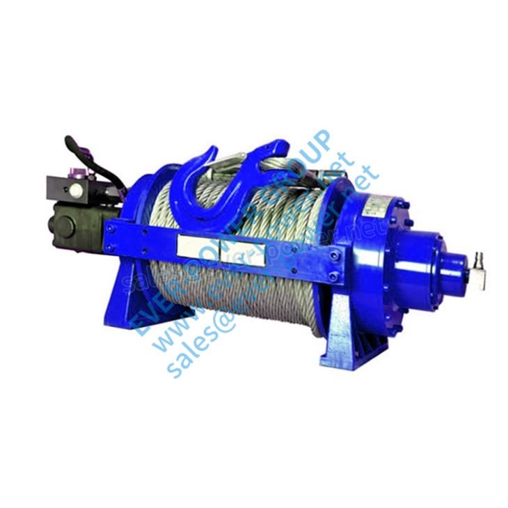
Ever-power Hydraulic Winches are tested and accredited to use in temperatures from -40° F to 120° F. Our winches provide easy, fast free spooling with only 50 lbs. resistance at -35ºF and can be managed by atmosphere or manually, offering fast collection payout and reducing use on parts.Ever-power Hydraulic Winches are produced to meet SAE J706 standards for all of us models and also to meet EN14492-1 standards for EU models.

Additional benefits include:

One lubricant for all-temperature operation to -35ºF
Compact design reduces cable catch between drum flange and end support housing
Lighter weight than comparable models while still offering legendary Ever-power durability and rugged construction
Level winders and cable tensioners are available for many models. Call factory to determine option of accessories for any specific winch.
2-speed motor on some models

ep

January 16, 2020

What exactly are Hydraulic Motors?
Hydraulic motors are rotary actuators that convert hydraulic, or fluid energy into mechanical power. They function in tandem with a hydraulic pump, which converts mechanical power into liquid, or hydraulic power. Hydraulic motors provide the force and supply the motion to go an external load.

Three common types of hydraulic motors are used most often today-gear, vane and piston motors-with a number of styles available included in this. In addition, several other types exist that are less commonly used, including gerotor or gerolor (orbital or roller celebrity) motors.

Hydraulic motors could be either set- or variable-displacement, and operate either bi-directionally or uni-directionally. Fixed-displacement motors drive lots at a continuous speed while a constant input flow is supplied. Variable-displacement motors can provide varying flow prices by changing the displacement. Fixed-displacement motors provide constant torque; variable-displacement styles provide variable torque and speed.

Torque, or the turning and twisting hard work of the push of the electric motor, is definitely expressed in in.-lb or ft-lb (Nm). Three various kinds of torque can be found. Breakaway torque is generally used to define the minimum torque required to begin a motor without load. This torque is founded on the inner friction in the engine and describes the initial “breakaway” drive required to begin the engine. Running torque creates enough torque to keep the motor or motor and load running. Starting torque is the minimal torque required to begin a engine under load and is definitely a mixture of energy required to overcome the push of the strain and internal electric motor friction. The ratio of actual torque to theoretical torque gives you the mechanical performance of a hydraulic engine.

Defining a hydraulic motor’s internal quantity is done simply by looking in its displacement, therefore the oil volume that is introduced into the motor during 1 output shaft revolution, in either in.3/rev or cc/rev, may be the motor’s volume. This is often calculated by adding the volumes of the electric motor chambers or by rotating the motor’s shaft one convert and collecting the essential oil manually, after that measuring it.

Flow rate is the oil volume that is introduced in to the motor per unit of time for a continuous output velocity, in gallons each and every minute (gpm) or liter per minute (lpm). This is often calculated by multiplying the electric motor displacement with the operating speed, or just by gauging with a flowmeter. You may also manually measure by rotating the motor’s shaft one convert and collecting the liquid manually.

Three common designs

Keep in mind that the three various kinds of motors have different characteristics. Gear motors work best at medium pressures and flows, and are often the cheapest cost. Vane motors, on the other hand, offer medium pressure ratings and high flows, with a mid-range cost. At the most costly end, piston motors offer the highest stream, pressure and efficiency ratings.
External gear motor.

Equipment motors feature two gears, one being the driven gear-which is attached to the result shaft-and the idler gear. Their function is easy: High-pressure oil is certainly ported into one aspect of the gears, where it flows around the gears and casing, to the outlet interface and compressed out from the engine. Meshing of the gears can be a bi-product of high-pressure inlet movement acting on the gear teeth. What in fact prevents liquid from leaking from the reduced pressure (outlet) aspect to high pressure (inlet) side may be the pressure differential. With gear motors, you must be concerned with leakage from the inlet to wall plug, which reduces motor performance and creates heat as well.

In addition with their low priced, gear motors do not fail as quickly or as easily as other styles, since the gears wear out the casing and bushings before a catastrophic failure can occur.

At the medium-pressure and cost range, vane motors include a housing with an eccentric bore. Vanes rotor slide in and out, run by the eccentric bore. The motion of the pressurized liquid causes an unbalanced push, which forces the rotor to carefully turn in one direction.
Piston-type motors can be found in a variety of different designs, including radial-, axial-, and other less common styles. Radial-piston motors feature pistons organized perpendicularly to the crankshaft’s axis. As the crankshaft rotates, the pistons are moved linearly by the fluid pressure. Axial-piston designs include a amount of pistons arranged in a circular design inside a housing (cylinder prevent, rotor, or barrel). This casing rotates about its axis by a shaft that is aligned with the pumping pistons. Two designs of axial piston motors exist-swashplate and bent axis types. Swashplate designs feature the pistons and drive shaft in a parallel set up. In the bent axis edition, the pistons are organized at an angle to the primary drive shaft.
Of the lesser used two designs, roller superstar motors offer lower friction, higher mechanical efficiency and higher start-up torque than gerotor designs. Furthermore, they offer smooth, low-speed operation and provide longer life with less wear on the rollers. Gerotors provide continuous fluid-restricted sealing throughout their even operation.
Specifying hydraulic motors
There are several considerations to consider when choosing a hydraulic motor.

You must know the utmost operating pressure, speed, and torque the motor will have to accommodate. Understanding its displacement and flow requirements within a system is equally important.

Hydraulic motors can use different types of fluids, and that means you got to know the system’s requirements-does it require a bio-based, environmentally-friendly fluid or fire resistant one, for example. In addition, contamination can be a problem, so knowing its resistance levels is important.

Cost is clearly a huge factor in any element selection, but initial price and expected life are simply one part of the. You must also know the motor’s efficiency ranking, as this will element in whether it runs cost-effectively or not. Furthermore, a component that is easy to restoration and keep maintaining or is easily changed out with various other brands will reduce overall system costs in the end. Finally, consider the motor’s size and weight, as this will effect the size and weight of the machine or machine with which it is being used.