An assembly of meshed gears comprising a central or sun equipment, a coaxial inner or ring equipment, and a number of intermediate pinions supported upon a revolving carrier. Occasionally the term planetary gear teach is used broadly as a synonym for epicyclic gear teach, or narrowly to point that the ring gear is the set member. In a simple planetary gear teach the pinions mesh simultaneously with both coaxial gears (find illustration). With the central equipment set, a pinion rotates about any of it as a world rotates about its sunlight, and the gears are named appropriately: the central gear may be the sun, and the pinions are the planets.
This is a compact, ‘single’ stage planetary gearset where in fact the output comes from another ring gear varying a few teeth from the primary.
With the initial model of 18 sun teeth, 60 band teeth, and 3 planets, this led to a ‘single’ stage gear reduction of -82.33:1.
A regular planetary gearset of the size could have a reduction ratio of 4.33:1.
That is a whole lot of torque in a small package.
At Nominal Voltage
Voltage (Nominal) 12V
Voltage Range (Recommended) 3V – 12V
Speed (No Load)* 52 rpm
Current (No Load)* 0.21A
Current (Stall)* 4.9A
Torque (Stall)* 291.6 oz-in (21 kgf-cm)
Gear Ratio 231:1
Gear Material Metal
Gearbox Style Planetary
Motor Type DC
Output Shaft Diameter 4mm (0.1575”)
Output Shaft Style D-shaft
Result Shaft Support Dual Ball Bearing
Electrical Connection Man Spade Terminal
Operating Temperature -10 ~ +60°C
Installation Screw Size M2 x 0.4mm
Product Weight 100g (3.53oz)
Within an epicyclic or planetary gear train, several spur gears distributed evenly around the circumference operate between a gear with internal teeth and a gear with exterior teeth on a concentric orbit. The circulation of the spur equipment occurs in analogy to the orbiting of the planets in the solar system. This is one way planetary gears obtained their name.
The elements of a planetary gear train could be split into four main constituents.
The housing with integrated internal teeth is actually a ring gear. In the majority of cases the casing is fixed. The driving sun pinion is usually in the heart of the ring equipment, and is coaxially arranged with regards to the output. Sunlight pinion is usually mounted on a clamping system in order to offer the mechanical link with the engine shaft. During procedure, the planetary gears, which are mounted on a planetary carrier, roll between the sun pinion and the ring gear. The planetary carrier also represents the output shaft of the gearbox.
The sole purpose of the planetary gears is to transfer the mandatory torque. The number of teeth does not have any effect on the transmitting ratio of the gearbox. The amount of planets can also vary. As the amount of planetary gears raises, the distribution of the load increases and therefore the torque that can be transmitted. Increasing the amount of tooth engagements also decreases the rolling power. Since just section of the total output needs to be transmitted as rolling power, a planetary equipment is incredibly efficient. The advantage of a planetary gear compared to a single spur gear lies in this load distribution. Hence, it is feasible to transmit high torques wit
h high efficiency with a concise design using planetary gears.
Provided that the ring gear has a constant size, different ratios can be realized by various the amount of teeth of sunlight gear and the number of the teeth of the planetary gears. Small the sun equipment, the greater the ratio. Technically, a meaningful ratio range for a planetary stage is approx. 3:1 to 10:1, because the planetary gears and the sun gear are extremely little above and below these ratios. Higher ratios can be acquired by connecting several planetary stages in series in the same band gear. In this instance, we speak of multi-stage gearboxes.
With planetary gearboxes the speeds and torques could be overlaid by having a ring gear that is not fixed but is driven in any direction of rotation. Additionally it is possible to repair the drive shaft in order to grab the torque via the band gear. Planetary gearboxes have grown to be extremely important in many regions of mechanical engineering.
They have grown to be particularly well established in areas where high output levels and fast speeds must be transmitted with favorable mass inertia ratio adaptation. High transmission ratios may also easily be achieved with planetary gearboxes. Because of their positive properties and small design, the gearboxes have many potential uses in commercial applications.
The benefits of planetary gearboxes:
Coaxial arrangement of input shaft and output shaft
Load distribution to many planetary gears
High efficiency because of low rolling power
Nearly unlimited transmission ratio options due to mixture of several planet stages
Appropriate as planetary switching gear because of fixing this or that part of the gearbox
Chance for use as overriding gearbox
Favorable volume output
Suitability for an array of applications
Within an epicyclic or planetary gear train, several spur gears distributed evenly around the circumference run between a gear with internal teeth and a gear with exterior teeth on a concentric orbit. The circulation of the spur equipment occurs in analogy to the orbiting of the planets in the solar program. This is how planetary gears acquired their name.
The parts of a planetary gear train can be divided into four main constituents.
The housing with integrated internal teeth is known as a ring gear. In the majority of cases the housing is fixed. The generating sun pinion is certainly in the heart of the ring gear, and is coaxially arranged in relation to the output. The sun pinion is usually mounted on a clamping system in order to offer the mechanical link with the motor shaft. During operation, the planetary gears, which are installed on a planetary carrier, roll between the sun pinion and the band equipment. The planetary carrier also represents the output shaft of the gearbox.
The sole purpose of the planetary gears is to transfer the required torque. The amount of teeth has no effect on the transmitting ratio of the gearbox. The amount of planets can also vary. As the number of planetary gears raises, the distribution of the load increases and therefore the torque which can be transmitted. Increasing the number of tooth engagements also reduces the rolling power. Since just area of the total output has to be transmitted as rolling power, a planetary equipment is incredibly efficient. The benefit of a planetary equipment compared to a single spur gear is based on this load distribution. Hence, it is feasible to transmit high torques wit
h high efficiency with a concise design using planetary gears.
Provided that the ring gear includes a continuous size, different ratios can be realized by various the amount of teeth of the sun gear and the amount of tooth of the planetary gears. Small the sun equipment, the higher the ratio. Technically, a meaningful ratio range for a planetary stage can be approx. 3:1 to 10:1, since the planetary gears and the sun gear are extremely small above and below these ratios. Higher ratios can be obtained by connecting several planetary stages in series in the same band gear. In cases like this, we talk about multi-stage gearboxes.
With planetary gearboxes the speeds and torques could be overlaid by having a ring gear that is not fixed but is driven in virtually any direction of rotation. Additionally it is possible to repair the drive shaft to be able to grab the torque via the band equipment. Planetary gearboxes have grown to be extremely important in many regions of mechanical engineering.
They have become particularly well established in areas where high output levels and fast speeds should be transmitted with favorable mass inertia ratio adaptation. High transmitting ratios can also easily be performed with planetary gearboxes. Because of their positive properties and small design, the gearboxes have many potential uses in commercial applications.
The benefits of planetary gearboxes:
Coaxial arrangement of input shaft and output shaft
Load distribution to many planetary gears
High efficiency because of low rolling power
Nearly unlimited transmission ratio options because of mixture of several planet stages
Suitable as planetary switching gear because of fixing this or that portion of the gearbox
Possibility of use as overriding gearbox
Favorable volume output
Suitability for an array of applications
Epicyclic gearbox is an automatic type gearbox where parallel shafts and gears set up from manual equipment box are replaced with more compact and more reliable sun and planetary kind of gears arrangement as well as the manual clutch from manual power train is replaced with hydro coupled clutch or torque convertor which produced the transmission automatic.
The idea of epicyclic gear box is taken from the solar system which is considered to an ideal arrangement of objects.
The epicyclic gearbox usually includes the P N R D S (Parking, Neutral, Invert, Drive, Sport) settings which is obtained by fixing of sun and planetary gears based on the require of the drive.
Within an epicyclic or planetary gear train, several spur gears distributed evenly around the circumference operate between a gear with internal teeth and a gear with external teeth on a concentric orbit. The circulation of the spur equipment occurs in analogy to the orbiting of the planets in the solar program. This is one way planetary gears obtained their name.
The parts of a planetary gear train can be split into four main constituents.
The housing with integrated internal teeth is known as a ring gear. In the majority of cases the casing is fixed. The traveling sun pinion is in the heart of the ring equipment, and is coaxially organized in relation to the output. Sunlight pinion is usually mounted on a clamping system to be able to offer the mechanical connection to the motor shaft. During operation, the planetary gears, which are mounted on a planetary carrier, roll between the sun pinion and the ring equipment. The planetary carrier also represents the output shaft of the gearbox.
The sole reason for the planetary gears is to transfer the mandatory torque. The amount of teeth has no effect on the transmitting ratio of the gearbox. The number of planets can also vary. As the number of planetary gears raises, the distribution of the load increases and then the torque which can be transmitted. Raising the number of tooth engagements also reduces the rolling power. Since just portion of the total result has to be transmitted as rolling power, a planetary gear is extremely efficient. The advantage of a planetary equipment compared to an individual spur gear is based on this load distribution. It is therefore possible to transmit high torques wit
h high efficiency with a compact design using planetary gears.
Provided that the ring gear includes a continuous size, different ratios could be realized by different the amount of teeth of sunlight gear and the amount of teeth of the planetary gears. The smaller the sun equipment, the greater the ratio. Technically, a meaningful ratio range for a planetary stage is certainly approx. 3:1 to 10:1, because the planetary gears and the sun gear are extremely small above and below these ratios. Higher ratios can be acquired by connecting a number of planetary stages in series in the same band gear. In this case, we speak of multi-stage gearboxes.
With planetary gearboxes the speeds and torques can be overlaid by having a ring gear that’s not set but is driven in any direction of rotation. Additionally it is possible to repair the drive shaft in order to grab the torque via the ring equipment. Planetary gearboxes have grown to be extremely important in many areas of mechanical engineering.
They have become particularly more developed in areas where high output levels and fast speeds must be transmitted with favorable mass inertia ratio adaptation. High transmission ratios may also easily be achieved with planetary gearboxes. Because of the positive properties and small design, the gearboxes possess many potential uses in commercial applications.
The benefits of planetary gearboxes:
Coaxial arrangement of input shaft and output shaft
Load distribution to several planetary gears
High efficiency because of low rolling power
Nearly unlimited transmission ratio options because of combination of several planet stages
Ideal as planetary switching gear due to fixing this or that portion of the gearbox
Possibility of use as overriding gearbox
Favorable volume output
In a planetary gearbox, many teeth are involved at once, that allows high speed decrease to be performed with relatively small gears and lower inertia reflected back to the engine. Having multiple teeth discuss the load also allows planetary gears to transmit high levels of torque. The combination of compact size, large speed decrease and high torque transmitting makes planetary gearboxes a favorite choice for space-constrained applications.
But planetary gearboxes do have some disadvantages. Their complexity in design and manufacturing tends to make them a far more expensive solution than various other gearbox types. And precision production is extremely important for these gearboxes. If one planetary gear is put closer to the sun gear than the others, imbalances in the planetary gears may appear, resulting in premature wear and failure. Also, the compact footprint of planetary gears makes heat dissipation more difficult, therefore applications that run at high speed or encounter continuous operation may require cooling.
When using a “standard” (i.e. inline) planetary gearbox, the motor and the driven equipment must be inline with one another, although manufacturers offer right-angle designs that include other gear sets (often bevel gears with helical tooth) to supply an offset between the input and output.
Input power (max)27 kW (36 hp)
Input speed (max)2800 rpm2
Output torque (intermittent)12,880 Nm(9,500 lb-ft)
Output torque (continuous)8,135 Nm (6,000 lb-ft)
1 Actual ratio is dependent on the drive configuration.
2 Max input speed linked to ratio and max result speed
3 Max radial load positioned at optimum load position
4 Weight varies with configuration and ratio selected
5 Requires tapered roller planet bearings (unavailable with all ratios)
Approximate dry weight100 -181 kg (220 – 400 lb)4
Radial load (max)14,287kg (31,500 lb)3
Drive typeSpeed reducer
Hydraulic motor input SAE C or D hydraulic
A planetary transmission program (or Epicyclic system since it can be known), consists normally of a centrally pivoted sunlight gear, a ring gear and several planet gears which rotate between these.
This assembly concept explains the word planetary transmission, as the earth gears rotate around the sun gear as in the astronomical sense the planets rotate around our sun.
The benefit of a planetary transmission depends upon load distribution over multiple planet gears. It is thereby feasible to transfer high torques employing a compact design.
Gear assembly 1 and equipment assembly 2 of the Ever-Power 500/14 possess two selectable sunlight gears. The first equipment step of the stepped planet gears engages with sun gear #1. The second gear step engages with sun gear #2. With sunlight gear one or two 2 coupled to the axle,or the coupling of sunlight equipment 1 with the ring gear, three ratio variations are achievable with each gear assembly.
Direct Gear 1:1
Example Gear Assy (1) and (2)
With direct equipment selected in equipment assy (1) or (2), sunlight gear 1 is in conjunction with the ring equipment in gear assy (1) or gear assy (2) respectively. Sunlight gear 1 and band gear then rotate jointly at the same rate. The stepped world gears do not unroll. Thus the apparatus ratio is 1:1.
Gear assy (3) aquires direct gear predicated on the same principle. Sun gear 3 and band gear 3 are directly coupled.
Many “gears” are utilized for automobiles, but they are also utilized for many various other machines. The most frequent one may be the “tranny” that conveys the energy of engine to tires. There are broadly two functions the transmission of an automobile plays : one can be to decelerate the high rotation quickness emitted by the engine to transmit to tires; the other is to change the reduction ratio in accordance with the acceleration / deceleration or traveling speed of a car.
The rotation speed of an automobile’s engine in the overall state of driving amounts to 1 1,000 – 4,000 rotations each and every minute (17 – 67 per second). Because it is impossible to rotate tires with the same rotation speed to perform, it is required to lower the rotation speed utilizing the ratio of the number of gear teeth. This kind of a role is named deceleration; the ratio of the rotation swiftness of engine and that of wheels is named the reduction ratio.
Then, exactly why is it necessary to modify the reduction ratio relative to the acceleration / deceleration or driving speed ? This is because substances require a large force to begin moving however they usually do not require this kind of a sizable force to excersice once they have started to move. Automobile could be cited as a good example. An engine, however, by its character can’t so finely modify its output. Therefore, one adjusts its result by changing the decrease ratio employing a transmission.
The transmission of motive power through gears very much resembles the principle of leverage (a lever). The ratio of the amount of the teeth of gears meshing with one another can be considered as the ratio of the length of levers’ arms. That is, if the reduction ratio is large and the rotation rate as output is low in comparison to that as insight, the power output by transmitting (torque) will be huge; if the rotation acceleration as output is not so lower in comparison to that as input, on the other hand, the power output by transmission (torque) will be little. Thus, to improve the decrease ratio utilizing transmission is much akin to the theory of moving things.
After that, how does a tranny change the reduction ratio ? The answer lies in the mechanism called a planetary gear mechanism.
A planetary gear system is a gear system comprising 4 components, namely, sun gear A, several planet gears B, internal gear C and carrier D that connects planet gears as seen in the graph below. It includes a very complex framework rendering its style or production most difficult; it can recognize the high decrease ratio through gears, nevertheless, it is a mechanism suited to a reduction system that requires both small size and powerful such as for example transmission for automobiles.
The planetary speed reducer & gearbox is a kind of transmission mechanism. It utilizes the velocity transducer of the gearbox to lessen the turnover quantity of the motor to the mandatory one and obtain a large torque. How does a planetary gearbox work? We can find out more about it from the framework.
The main transmission structure of the planetary gearbox is planet gears, sun gear and band gear. The ring equipment is located in close get in touch with with the internal gearbox case. Sunlight equipment driven by the external power lies in the center of the ring gear. Between your sun gear and ring gear, there is a planetary equipment set consisting of three gears similarly built-up at the earth carrier, which can be floating among them counting on the support of the result shaft, ring gear and sun equipment. When sunlight equipment is actuated by the insight power, the planet gears will be powered to rotate and then revolve around the guts together with the orbit of the band equipment. The rotation of the planet gears drives the output shaft connected with the carrier to output the power.
Planetary speed reducer applications
Planetary speed reducers & gearboxes have a lot of advantages, like small size, light weight, high load capability, long service life, high reliability, low noise, huge output torque, wide selection of speed ratio, high efficiency and so forth. Besides, the planetary velocity reducers gearboxes in Ever-Power are created for square flange, which are easy and hassle-free for installation and ideal for AC/DC servo motors, stepper motors, hydraulic motors etc.
Because of these advantages, planetary gearboxes can be applied to the lifting transportation, engineering machinery, metallurgy, mining, petrochemicals, construction machinery, light and textile industry, medical equipment, device and gauge, automobile, ships, weapons, aerospace and other industrial sectors.
The primary reason to employ a gearhead is that it creates it possible to control a big load inertia with a comparatively small motor inertia. Without the gearhead, acceleration or velocity control of the load would require that the electric motor torque, and thus current, would need to be as much times higher as the reduction ratio which is used. Moog offers a selection of windings in each frame size that, coupled with a selection of reduction ratios, offers an assortment of solution to result requirements. Each mixture of motor and gearhead offers unique advantages.
Precision Planetary Gearheads
gearheads
32 mm LOW PRICED Planetary Gearhead
32 mm Precision Planetary Gearhead
52 mm Precision Planetary Gearhead
62 mm Precision Planetary Gearhead
81 mm Precision Planetary Gearhead
120 mm Precision Planetary Gearhead
Planetary gearheads are ideal for transmitting high torques as high as 120 Nm. Generally, the larger gearheads come with ball bearings at the gearhead result.
Properties of the Ever-Power planetary gearhead:
– For transmitting of high torques up to 180 Nm
– Reduction ratios from 4:1 to 6285:1
– High efficiency in the tiniest of spaces
– High reduction ratio in an extremely small package
– Concentric gearhead input and output
Versions:
– Plastic version
– Ceramic version
– High-power gearheads
– Heavy-duty gearheads
– Gearheads with minimal backlash
80mm size inline planetary reducer for NEMA34 (flange 86mm) or NEMA42 stepper motor. Precision significantly less than 18 Arcmin. High torque, compact size and competitive cost. The 16mm shaft diameter ensures balance in applications with belt transmission. Fast installation for your equipment.
80mm size inline planetary reducer for NEMA34 (flange 86mm) or NEMA42 stepper motor. Precision significantly less than 18 Arcmin. High torque, small size and competitive cost. The 16mm shaft diameter ensures balance in applications with belt transmitting. Fast mounting for your equipment.
1. Planetary ring gear material: metal steel
2. Bearing at output type: Ball bearing
3. Max radial load (12mm distance from flange): 550N
4. Max shaft axial load: 500N
5. Backlash: 18 arcmin
6. Gear ratio from 3 to 216
7. Planetary gearbox length from 79 to 107mm
NEMA34 Precision type Planetary Gearbox for nema 34 Gear Stepper Motor 50N.m (6944oz-in) Rated Torque
This gear ratio is 5:1, if need other gear ratio, please e mail us.
Input motor shaft Planetary Gear Transmission demand :
suitable with regular nema34 stepper engine shaft 14mm diameter*32 length(Including pad height). (plane and Round shaft and essential shaft both available)
The difference between your economical and precision Nema34 planetary reducer:
To begin with: the financial and precise installation strategies are different. The insight of the cost-effective retarder assembly may be the keyway (ie the output shaft of the electric motor is an assembleable keyway motor); the insight of the precision reducer assembly is certainly clamped and the input electric motor shaft is a flat or circular shaft or keyway. The shaft could be mounted (note: the keyway shaft could be removed following the key is removed).
Second, the economical and precision planetary gearboxes possess the same drawings and measurements. The primary difference is: the materials differs. Accurate gear units are more advanced than economical gear units in conditions of transmission efficiency and accuracy, as well as heat and noise and torque output balance.
 on the basic principle of induction where a rotating electro-magnetic field it developed by applying a three-stage current at the stators electromagnets. This in turn induces a current within the rotor’s conductors, which in turns creates rotor’s magnetic field that attempts to check out stator’s magnetic field, pulling the rotor into rotation.
 motors are Asynchronous Machines meaning that the rotor will not change at the specific same speed since the stator’s rotating magnetic field. Some difference in the rotor and stator acceleration is necessary in order to make the induction in to the rotor. The difference between the two is named the slip. Slip should be kept in a optimal range in order for the motor to operate efficiently. Roboteq AC Induction controllers could be configured to operate in another of three modes:
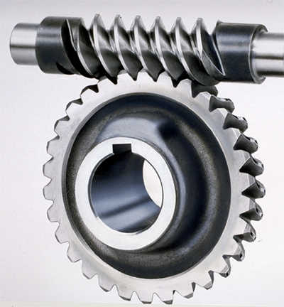 precision grinding, carburization layer’s thickness between 0.3-0.5mm.
 push demands significantly less electrical power in the course of the commence-up of the engine and has standardisation of bores for uniform shafts of the electrical motors. With a delay chamber, the interior wheel travel also has a sluggish-start off up as the oil is sucked into the workspace. Alternatively, the outer wheel travel has excellent warmth dissipation which makes it best for apps with regular or long commencing processes. The outer wheel also has an simpler oil placing, which indicates that it can be turned out wit
 hout having shifting the generate or the pushed equipment.
 teeth that are directly and oblique.
 about 1800 rpm at 2.0 volts. It is smaller and faster than our low speed DC motor.
  6′ rotary cutters. I sell a lot of these bins every single calendar year for a number of distinct apps and carry ALL Replacement Parts for this box, but hopefully you will not have to fear about that.
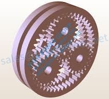 role is named deceleration; the ratio of the rotation swiftness of engine and that of wheels is named the reduction ratio.